


|
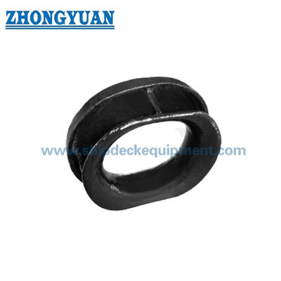
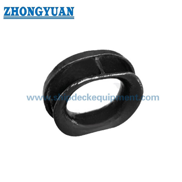
Bulwark-Mounted Cast Steel Mooring Chock | ISO 13713 Type B for Mooring and Towing
Product Details:
| Place of Origin: | China |
| Brand Name: | Zhongyuan Marine Equipmen |
| Certification: | CCS, NK, BV, ABS, DNV, LR, KR, IRS, RS, RINA, CRS, Makers Test Certificate |
| Model Number: | Standard or Customized |
Payment & Shipping Terms:
| Minimum Order Quantity: | 1 Unit |
|---|---|
| Price: | Based on quotation |
| Packaging Details: | Export standard pallet or customized packing |
| Delivery Time: | Based on project requirements |
| Payment Terms: | T/T, L/C |
| Supply Ability: | Customized production based on project requirements |
|
Detail Information |
|||
| Standard: | ISO 13713 | Type: | B; Bulwark Mounted Type |
|---|---|---|---|
| SWL Range: | 36 To 140 T | Materials: | Casting C-Mn Steel, Casting Stainless Steel, Also Can Supply Special Steel For Icebreaker. |
| Weight: | 48-266kg | Surface Treatment: | Sandblasting To S2.5 + One Layer Of Epoxy Shop Primer, Polished Stainless Steel, Customized Surface Treatment Available |
| Classification Certificates: | CCS, NK, BV, ABS, DNV, LR, KR, RINA, IRS | ||
| Highlight: | iso 13713 mooring chock,abs mooring chock,iso 13713 ship towing equipment |
||
Product Description
Bulwark-Mounted Cast Steel Mooring Chock | ISO 13713 Type B for Mooring and Towing
Product Overview
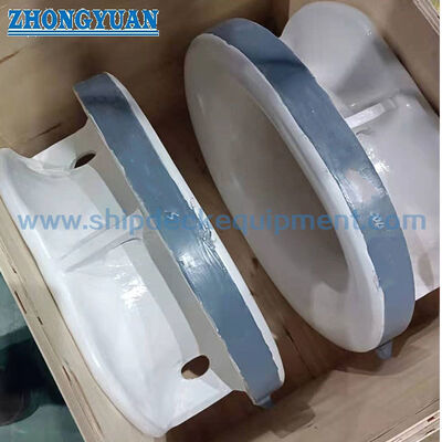
The ISO 13713 Type B mooring chock is a bulwark-mounted cast steel rope guide used to lead a mooring line from the vessel inboard side to the outboard side through a smooth closed opening. The cast body is welded into the bulwark structure, so the vessel designer or shipyard should confirm the surrounding reinforcement, weld arrangement, line lead direction, and local load transfer before installation.
This Type B configuration is normally selected for nylon and other synthetic mooring ropes. Because rope strength can be reduced when the line bends through the chock, the selected size and contact radius should be checked against the rope manufacturer’s minimum bend-radius and strength-reduction guidance. For wire-rope arrangements, the applicable closed-chock standard and vessel design requirement should be confirmed separately.
Quick Specifications
- Standard and type: ISO 13713 Type B → bulwark-mounted welded mooring chock for leading the line through the ship side.
- Nominal size range: 250 × 200 to 500 × 250B → seven standard size/load combinations for different mooring arrangements.
- Reference SWL range: 353 to 1373 kN (36 to 140 t) → table values are reference ratings; actual marking depends on the approved loading condition.
- Calculated weight: 48 to 266 kg → useful for lifting plans, installation handling, packing, and freight estimation.
- Material options: cast C-Mn steel or cast stainless steel → low-temperature special cast steel for ice-service projects requires grade and impact requirements to be confirmed.
- Surface treatment: abrasive blasting to Sa 2.5 + one coat epoxy shop primer → final coating follows the vessel paint specification; stainless steel finish can be polished when specified.
- Engineering focus: smooth rope-contact radius, controlled casting quality, correct rope lead, equivalent weld strength, and adequate bulwark reinforcement.
Main Technical Parameters
| Nominal size L x H |
I1 | I2 | B | H1 | H2 | C | R | R1 | R2 |
| 250 X 200 | 450 | 398 | 154 | 408 | 327 | 57 | 100 | 200 | 174 |
| 300 X 250 | 516 | 460 | 168 | 466 | 387 | 60 | 125 | 233 | 205 |
| 350 X250 | 582 | 520 | 177 | 482 | 395 | 65 | 125 | 241 | 210 |
| 400 X 250 | 652 | 588 | 193 | 502 | 412 | 70 | 125 | 251 | 219 |
| 450 X 250 | 734 | 662 | 213 | 534 | 433 | 77 | 125 | 267 | 231 |
| 500 X 250A | 812 | 730 | 237 | 562 | 447 | 82 | 125 | 281 | 240 |
| 500 X 2508 | 828 | 750 | 253 | 578 | 466 | 82 | 125 | 289 | 250 |
| Nominal size L x H |
R3 | T | T1 | Welding leg length a | SWL b | Calculated weight c | |||
| z1 | z2 | kN | t | kg | |||||
| 250 X 200 | 78 | 26 | 20 | 8 | 8 | 353 | 36 | 48 | |
| 300 X 250 | 85 | 27 | 24 | 8 | 9,5 | 491 | 50 | 83 | |
| 350 X 250 | 90 | 29 | 25 | 9 | 10 | 589 | 60 | 100 | |
| 400 X 250 | 98 | 34 | 32 | 9,5 | 13 | 736 | 75 | 145 | |
| 450 X 250 | 108 | 41 | 36 | 12,5 | 14,5 | 981 | 100 | 215 | |
| 500 X 250A | 120 | 41 | 36 | 12,5 | 14,5 | 1128 | 115 | 235 | |
| 500 X 2508 | 128 | 48 | 41 | 14,5 | 16,5 | 1373 | 140 | 266 | |
| a The welding method may be changed based on the same welding volume/strength. b The SWLs shown are for reference only. The "SWL" which is marked on the fitting may be adjusted depending on the actual loading cond1t10ns of mooring rope under the agreement between the user and the manufacturer. C The calculated weight (mass) is for reference only. |
|||||||||
Selection & Inquiry Guide
Step 1: Confirm ISO 13713 Type B, nominal size, and whether the vessel arrangement requires a bulwark-mounted chock rather than a deck-mounted fitting.
Step 2: Provide rope type, diameter, construction, MBL, rope manufacturer, minimum bend-radius requirement, and any stated strength-reduction factor.
Step 3: Provide the vessel design load, expected horizontal and vertical line lead angles, and required fitting marking so that the reference SWL is not used outside the approved loading condition.
Step 4: Confirm the bulwark opening, supporting structure, reinforcement, installation position, welding access, weld profile, and applicable shipyard or class welding procedure.
Step 5: Confirm material grade, minimum design temperature or ice-class requirement, surface treatment, final coating system, and stainless-steel polishing requirement if applicable.
Step 6: Provide quantity, certificate and inspection scope, vessel type, drawing or photo, delivery destination, and required delivery time.
Structure
Closed cast rope opening | Smooth rope-contact radius | Bulwark-mounted cast body | Welded connection zones | Local supporting and reinforcement structure | Primer or stainless-steel finish
Casting, Rope Contact and Installation Advantages
- The closed opening controls the rope path through the bulwark and provides a continuous rounded contact surface instead of a sharp plate edge.
- Rope-contact surfaces are dressed and smoothed after casting to remove harmful sharp edges, roughness, or irregularities that could accelerate abrasion.
- The size series combines increasing contact radii, wall dimensions, reference SWL, weld-leg requirements, and casting mass for progressive mooring-load ranges.
- The chock is welded into the vessel structure; line contact force is transferred through the cast body and weld zones into the reinforced bulwark, making supporting-structure review essential.
- Where a different weld method is proposed, equivalent weld volume and strength should be demonstrated and accepted by the vessel designer, shipyard, and class as applicable.
- Casting inspection, material traceability, NDT scope, dimensional checks, coating inspection, and witness requirements can be arranged according to the agreed project and classification scope.
Custom Attributes
- Standard: ISO 13713 → standard reference for the Type B ship-side mooring chock dimensions and reference ratings.
- Type: Type B, bulwark-mounted → selected when the mooring line passes through the vessel bulwark from inboard to outboard.
- Nominal Size: 250 × 200 to 500 × 250B → select by rope arrangement, line load, contact radius, available space, and approved vessel drawing.
- Reference SWL: 36 / 50 / 60 / 75 / 100 / 115 / 140 t → actual fitting marking is subject to the agreed loading condition.
- Material: Cast C-Mn steel / cast stainless steel / special low-temperature cast steel → exact grade, impact properties, and traceability scope to be confirmed.
- Surface Treatment: Sa 2.5 blasting + epoxy shop primer / polished stainless steel / project coating → final system follows order specification.
- Inspection and Certification: Available according to project requirement → certificate type, class witnessing, NDT, and material documentation must be defined before quotation.
How It Works
Mooring line approaches the bulwark → Line passes through the closed Type B chock → Rounded contact surface controls the rope path and bend → Contact force is transferred through the cast body and welds → Reinforced bulwark structure distributes the load into the hull
Applications
Ship-side mooring stations | Bulwark rope openings | Synthetic mooring lines | Cargo vessels | Tankers | Bulk carriers | Container vessels | Tug and workboat mooring arrangements | Newbuilding and replacement projects
Certifications & Advantages
Certificates can be arranged according to project requirement, inspection scope, material traceability, and class society approval procedure. Availability is subject to order scope and class approval.
Certification: CCS, NK, BV, ABS, DNV, LR, KR, IRS, RS, RINA, CRS, Makers Test Certificate.
Drawing & Photos

FAQ
Q1: How should the correct ISO 13713 Type B size be selected?
A1: Use the vessel mooring arrangement, rope type and diameter, rope MBL, manufacturer bend-radius guidance, line lead angles, design load, bulwark space, weld details, and supporting-structure approval. The standard SWL values are reference values, not a substitute for checking the actual loading condition.
Q2: Is this Type B chock suitable for wire rope?
A2: It is normally used with nylon or other synthetic ropes because the available bend ratio may not be suitable for wire rope. For wire-rope service, confirm the applicable closed-chock standard, rope construction, minimum sheave or bend diameter, vessel design, and class requirement.
Q3: Can the chock be treated as a towing or lifting point?
A3: It is not a lifting point. Towing duty should not be assumed from the reference mooring SWL; any towing application requires separate confirmation of the load case, line direction, rope system, welds, hull reinforcement, and classification approval.