


|
Marine Electric Mooring Capstan with Horizontal Motor Drive | Deck-Mounted Warping Capstan
Product Details:
| Place of Origin: | China |
| Brand Name: | Zhongyuan Marine Equipmen |
| Certification: | CCS, NK, BV, ABS, DNV, LR, KR, IRS, RS, RINA, CRS, Makers Test Certificate |
| Model Number: | Standard or Customized |
Payment & Shipping Terms:
| Minimum Order Quantity: | 1 Unit |
|---|---|
| Price: | Based on quotation |
| Packaging Details: | Export standard pallet or customized packing |
| Delivery Time: | Based on project requirements |
| Payment Terms: | T/T, L/C |
| Supply Ability: | Customized production based on project requirements |
|
Detail Information |
|||
| Function: | Mooring | Working Load: | 5KN To 250KN |
|---|---|---|---|
| Warping Head Diameter: | 200-700 Mm | Warping Speed(m/min): | 9-18m/Min |
| Wire Rope Dia.: | 11 - 46 (mm) | Material: | Stainless Steel (Polished), Mild Steel, Casting |
| Power: | Electric | Control: | Local Or Remote Control |
| Classification Certificates: | CCS, NK, BV, ABS, DNV, LR, KR, IRS, RS, RINA, Etc | ||
| Highlight: | Ship Deck Equipment Capstan,Horizontal mooring capstan,Marine mooring capstan |
||
Product Description
Marine Electric Mooring Capstan with Horizontal Motor Drive | Deck-Mounted Warping Capstan
Product Overview
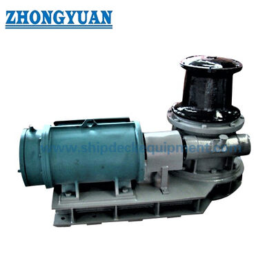
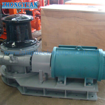
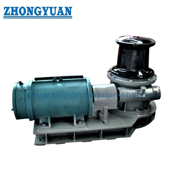
This marine electric mooring capstan is a deck-mounted line-handling machine for heaving and paying out mooring ropes during berthing, unberthing, shifting, and routine mooring operations. A vertical warping head is driven through a reduction gearbox by a horizontally arranged electric motor. The arrangement keeps the principal drive components accessible above deck where the project GA drawing adopts this configuration, while the capstan base is secured to a prepared shipboard foundation.
Unlike a drum mooring winch, the warping head is not a rope-storage drum. Hauling force is developed by friction between the mooring line and the rotating warping head while the free tail is handled in accordance with the vessel’s mooring procedure. Selection therefore needs to combine required pull and speed with rope type and diameter, warping-head profile, line lead, electrical supply, control arrangement, foundation reactions, maintenance access, and the vessel’s approved mooring arrangement.
Quick Specifications
- Function: Mooring / warping → intended for controlled line handling; it should not be described as a rope-storage winch.
- Drive arrangement: Horizontal electric motor + reduction gearbox → supports above-deck access to the drive train where confirmed by the GA arrangement.
- Catalogue model range: ZY-3T to ZY-10T → model designations indicate 3, 5, 8 and 10 tonne-class pull configurations; exact rated pull is to be confirmed from the final datasheet.
- Warping-head diameter: 330–510 mm in the supplied model table → the selected head must remain compatible with the actual rope construction and bend-radius requirement.
- Reference speeds: 10 / 15 m/min in the supplied model table → the table appears to represent two operating-speed / motor-power combinations and requires final manufacturer confirmation.
- Electric motor power: 7.5–30 kW in the supplied model table → corrected from the source heading “Power (KN.)”; final motor rating depends on model, speed and duty.
- Control: Local or remote according to project requirement → final control station, emergency stop, interlocks and visibility requirements are project-specific.
- Installation: Bolted equipment base on prepared foundation → holding-down bolts, deck reinforcement and foundation reactions must be confirmed by the vessel design / approved installation drawing.
Main Technical Parameters
| Model |
Pull (MT) |
Speed (M/MIN) |
Warping Head Dia. (mm) |
Power (KN.) |
| ZY-3T/330 | 3 | 10 | 330 | 7.5 |
| 15 | 11 | |||
| ZY-5T/330 | 5 | 10 | 330 | 11 |
| 15 | 15 | |||
| ZY-5T/380 | 10 | 380 | 11 | |
| 15 | 15 | |||
| ZY-8T/380 | 8 | 10 | 380 | 18.5 |
| 15 | 30 | |||
| ZY-8T/450 | 10 | 450 | 18.5 | |
| 15 | 30 | |||
| ZY-10T/450 | 10 | 10 | 450 | 22 |
| 15 | 30 | |||
| ZY-10T/510 | 10 | 510 | 22 | |
| 15 | 30 |
Selection & Inquiry Guide
Step 1: Confirm vessel type, installation position, required rated pull, warping speed, operating duty, and whether the capstan is for normal mooring / warping only.
Step 2: Confirm rope type, construction, diameter, MBL / LDBF where applicable, rope manufacturer D/d guidance, line direction, nearby rollers / fairleads, and required warping-head diameter or profile.
Step 3: Confirm ship electrical supply: voltage, frequency, phase, motor duty, required speed arrangement, starting method / VFD if required, enclosure protection, insulation class, and any hazardous-area requirement.
Step 4: Confirm local / remote control, emergency-stop locations, operator visibility, communication requirements, and any project-specific brake, interlock or restart-prevention requirement.
Step 5: Provide foundation / deck arrangement, mounting space, rope lead height, access for motor and gearbox maintenance, and approved foundation or GA drawing when available.
Step 6: Confirm material and coating requirements, quantity, classification society, inspection / test scope, certificate requirement, delivery destination, required delivery time, and reference drawings or photos.
Structure
Vertical warping head | Horizontal electric motor | Reduction gearbox | Shaft and bearing arrangement | Coupling as applicable | Equipment base / support frame | Bolted shipboard foundation | Local / remote control equipment
Mooring, Drive & Installation Advantages
- The vertical warping head provides a compact line-handling point without using a dedicated rope-storage drum, which can suit bow, stern and side mooring stations where deck layout is constrained.
- The horizontal motor / gearbox arrangement can improve direct maintenance access where the GA layout keeps the drive components above deck; actual removal space and service access should be checked before foundation approval.
- Warping-head selection can be matched to the intended rope rather than treated as a cosmetic model difference. ISO 6482:2017 covers warping-end types, nominal sizes, dimensions, markings and selection rules for deck machinery.
- Line lead should be reviewed together with nearby chocks, fairleads and rollers. Avoidable rubbing, excessive change of direction and poor operator position can reduce practical mooring-system performance even when capstan pull is adequate.
- Foundation design is part of the equipment integration. Warping-head pull creates torque and horizontal reactions that must be transferred through the base, holding-down bolts, supporting foundation and local hull structure.
- Inspection and maintainability should cover the warping surface, gearbox lubricant, bearings, coupling, fasteners, seals, motor, electrical enclosure, controls and foundation connection rather than focusing only on motor power.
Custom Attributes
- Function: Mooring / warping → line-handling duty; not a rope-storage function.
- Drive: Electric, horizontal motor arrangement → final motor orientation and coupling arrangement to follow approved GA drawing.
- Rated Pull: Model-dependent → keep separate from rope MBL / LDBF, fitting SWL and foundation design load.
- Warping Head: 330–510 mm in supplied model table → final profile and diameter to be checked against the selected rope.
- Speed: 10 / 15 m/min in supplied model table → exact speed-control arrangement to be confirmed.
- Material: To be confirmed → source webpage lists stainless steel, mild steel and casting generically, but component-specific material grades are not defined.
- Control: Local or remote → final control philosophy and safety functions according to project requirement.
- Installation: Bolted to prepared foundation → bolt arrangement, deck reinforcement and equipment reactions require project drawing confirmation.
- Standards Reference: ISO 7825:2017 / ISO 6482:2017 where contractually applicable → final governing standard and class rules to be stated in the purchase specification.
How It Works
Electric motor starts → Reduction gearbox transmits torque to the vertical warping head → Mooring line takes controlled turns around the warping surface → Friction develops hauling force while the free tail is managed → Line is heaved or paid out through the vessel’s mooring lead arrangement → Operator stops / controls the capstan according to the approved mooring procedure
Applications
Bow mooring stations | Stern mooring stations | Ship-side line-handling stations | Merchant vessels | Tankers | Bulk carriers | Cargo vessels | Workboats | Barges | Tug and service vessels | Newbuilding and retrofit mooring systems
Certifications & Advantages
Class survey, material documentation, maker’s test certificate, factory inspection, and witnessed function / load testing can be arranged according to project requirement, approved drawings, agreed inspection plan, and class approval scope. These documents should not be treated as automatically included with every supply.
Certification: CCS, NK, BV, ABS, DNV, LR, KR, IRS, RS, RINA, CRS, Makers Test Certificate.
Drawing & Photos

FAQ
Q1: Is the capstan pull the same as the mooring line MBL or a deck fitting SWL?
A1: No. Rated capstan pull is the hauling force available at the warping head under stated operating conditions. Mooring-line MBL / LDBF, Ship Design MBL, fitting SWL, test load and foundation design load are different engineering values and should remain separately defined.
Q2: How should the warping-head diameter be selected?
A2: Confirm the actual rope type, construction and diameter first, then check the rope manufacturer’s bend-radius / D/d guidance and the applicable warping-end profile requirement. ISO 6482:2017 is a relevant reference for warping-end profiles, but the final selection must match the project rope and approved mooring arrangement.
Q3: What information is essential before quotation?
A3: Provide required pull and speed, rope data, warping-head requirement, vessel electrical supply, control arrangement, installation / foundation drawing, class and test scope, quantity, destination and required delivery time. The three TBC pull entries in the current source table should also be confirmed before the parameter table is released as final.