


|
Closed Type Four-Roller Marine Fairlead for Engineering Vessels | CB 3015-1983 Type B Upper and Lower Horizontal Roller Arrangement
Product Details:
| Place of Origin: | China |
| Brand Name: | Zhongyuan Marine Equipmen |
| Certification: | CCS, NK, BV, ABS, DNV, LR, KR, IRS, RS, RINA, CRS, Makers Test Certificate |
| Model Number: | Standard or Customized |
Payment & Shipping Terms:
| Minimum Order Quantity: | 1 Unit |
|---|---|
| Price: | Based on quotation |
| Packaging Details: | Export standard pallet or customized packing |
| Delivery Time: | Based on project requirements |
| Payment Terms: | T/T, L/C |
| Supply Ability: | Customized production based on project requirements |
|
Detail Information |
|||
| Standard: | CB* 3015-83 | Type: | Type B, 2 Vertical Rollers, 1 Bottom & 1 Upper Horizontal Rollers |
|---|---|---|---|
| Roller Diameters: | 100mm To 300mm | Applications: | Dredgers, Crane Ships, Piling Boats And Other Engineering Vessels |
| Materials: | C-Mn Steel, Mild Steel, Stainless Steel | Surface Treatment: | Sandblasting To S2.5 + 3 Layers Of Epoxy Paint, Galvanized |
| Classification Certificates: | CCS, NK, BV, ABS, DNV, LR, KR, RINA, IRS, RS, Etc | ||
| Highlight: | cb/t 3015-83 type b marine fairlead,4 steel rollers marine fairlead,engineering vessel fairlead |
||
Product Description
Closed Type Four-Roller Marine Fairlead for Engineering Vessels | CB 3015-1983 Type B Upper and Lower Horizontal Roller Arrangement
Product Overview
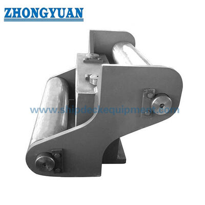
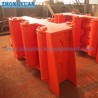
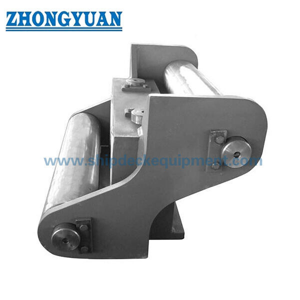
The CB 3015-1983 Type B marine fairlead is a closed-type four-roller steel wire rope guide developed for engineering-vessel deck arrangements. Its two vertical rollers and upper and lower horizontal rollers form an enclosed rope passage that guides a running wire rope from different lead directions, helps reduce direct sliding against fixed steel edges, and keeps the rope within the fairlead opening during winch, towing, positioning, or deck-working operations.
Typical vessel applications include dredgers, crane ships, piling vessels, engineering barges, salvage and work vessels, and other ships using steel-wire-rope deck machinery. The fairlead is a passive guiding component and does not generate pulling force. Final selection must therefore consider the actual wire rope, winch line pull, rope lead and change-of-direction angle, duty cycle, roller reactions, mounting structure, and project inspection requirement—not roller diameter alone.
Quick Specifications
• Standard reference: CB* 3015-83 Type B → dimensional and arrangement reference supplied by the user; reference for Type B arrangement and principal dimensions.
• Roller arrangement: Closed type arrangement with 2 vertical rollers + 1 upper horizontal roller + 1 lower horizontal roller → creates an enclosed four-sided guide opening for changing rope lead in multiple directions.
• Vertical roller diameter D: 100 to 300 mm → provides five dimensional models for different wire-rope and deck-layout requirements.
• Horizontal roller diameter D1: 85 to 250 mm → supports upper and lower rope contact when the line rises, falls, or moves within the guide opening.
• Main envelope: L 540 to 1460 mm, B 340 to 900 mm, H 240 to 675 mm → supports preliminary foundation-space, access, and installation planning.
• Materials: C-Mn steel, mild steel, or stainless steel as specified → exact grades, roller construction, shafts, bushings or bearings, and material traceability require drawing confirmation.
• Surface treatment: abrasive blast cleaning to Sa 2.5 with one coat of epoxy shop primer, polishing, galvanizing, or project-specific finish → select according to material and vessel coating system.
• Certification: maker documentation or class-related inspection can be arranged according to project requirement and agreed scope; certificates are not assumed to be automatically included.
Main Technical Parameters
Main dimensions for CB* 3015-83 Type B four-roller marine fairlead. Dimensions are in mm. Dimension letters must be read together with the approved standard drawing or GA drawing.
|
Vertical Roller |
Horizontal Roller |
Applicable Steel Wire |
L |
B |
H |
b |
h1 |
h2 |
l |
d |
|---|---|---|---|---|---|---|---|---|---|---|
| 100 | 85 | 19.5 | 540 | 340 | 240 | 250 | 220 | 50 | 200 | 22 |
| 150 | 120 | 26.0 | 760 | 460 | 340 | 340 | 320 | 65 | 290 | 26 |
| 200 | 150 | 37.5 | 980 | 580 | 440 | 430 | 410 | 80 | 380 | 32 |
| 250 | 200 | 48.5 | 1220 | 740 | 550 | 540 | 500 | 110 | 480 | 39 |
| 300 | 250 | 56.0 | 1460 | 900 | 675 | 650 | 590 | 135 | 580 | 39 |
Selection & Inquiry Guide
Step 1: Confirm CB* 3015-83 Type B, the required roller diameter D, and whether the four-roller enclosed arrangement matches the vessel rope-routing drawing.
Step 2: Provide steel wire rope data: nominal diameter, construction, core, lay, grade, minimum breaking load, operating condition, and rope manufacturer’s allowable bending or contact requirements.
Step 3: Confirm the machinery and load case: towing winch, positioning winch, anchor-handling or deck-working winch, maximum line pull, brake holding load, operating speed, dynamic factor, duty cycle, and change-of-direction angle.
Step 4: Provide the incoming and outgoing rope directions, expected side lead and vertical lead, fairlead location, available deck or bulwark space, and adjacent equipment arrangement.
Step 5: Confirm material grades, roller construction, shaft and bearing or bushing arrangement, lubrication method, surface treatment, mounting type, weld or bolt details, and supporting-structure reinforcement.
Step 6: Confirm quantity, certificate and inspection scope, NDT or load-test requirement, vessel type, classification society requirement, delivery destination, required delivery time, and approved drawing or reference photo.
Structure
Closed rope passage arrangement | Two vertical steel rollers | Upper horizontal roller | Lower horizontal roller | Roller shafts | Bearings or bushings | Side frames and cross members | Mounting base or welded support | Lubrication and retention arrangement as specified
Type B closed structure provides a more enclosed rope path compared with Type A, with upper and lower horizontal rollers controlling vertical rope movement.
Wire Rope Guidance, Installation & Quality Advantages
• The four rollers form an enclosed guide opening. Vertical rollers control side lead, while the upper and lower rollers support rope contact caused by upward or downward lead, helping the rope remain within a defined route.
• Rolling contact reduces direct sliding over fixed edges, but the actual rope-contact condition still depends on roller diameter, groove or barrel profile, rope tension, lead angle, roller rotation, and surface condition.
• The roller arrangement is suited to engineering-vessel layouts where the rope may approach or leave the fairlead at changing horizontal and vertical angles. The approved arrangement drawing should define the normal and extreme rope paths.
• Rope tension through a direction change produces reactions at the contacted rollers, shafts, bearings or bushings, frame, mounting welds or bolts, and supporting hull structure. These reactions must be calculated from the actual load case.
• Roller surfaces should be free from sharp edges and harmful local damage. Shafts, bearings or bushings, seals, grease points, retainers, and replacement access should be confirmed for inspection and maintenance.
• For towing or other dynamic service, transient line loads, vessel motions, shock loading, operating limits, and class requirements may govern selection. The product should not be rated only by the listed rope diameter.
• Material, welding, NDT, dimensional inspection, roller free-rotation checks, coating, marking, and documentation should follow the approved manufacturing and inspection plan.
Custom Attributes
• Standard: CB* 3015-83 Type B → use as the dimensional reference when specified by the vessel or shipyard; present-day acceptance is to be confirmed.
• Roller Configuration: Four rollers → two vertical rollers plus upper and lower horizontal rollers create a controlled rope passage.
• Vertical Roller Diameter D: 100 / 150 / 200 / 250 / 300 mm → preliminary model designation from the supplied table.
• Horizontal Roller Diameter D1: 85 / 120 / 150 / 200 / 250 mm → matched to the corresponding vertical-roller model.
• Applicable Wire Rope Diameter: According to supplied table → 176 mm and 370 mm entries require verification and must not be treated as confirmed values.
• Material: C-Mn steel / mild steel / stainless steel → exact grade, fabrication method, weldability, shaft material, and traceability are to be confirmed.
• Surface Treatment: Sa 2.5 blasting + epoxy shop primer / polished / galvanized / customized → final system depends on material and vessel coating specification.
• Load Basis: To be confirmed → provide winch line pull, rope MBL, lead angle, dynamic factor, duty, roller reaction, and foundation design data.
• Certificate Requirement: According to project scope → maker certificate, material certificate, inspection report, or class product certification should be agreed before quotation.
How It Works
Steel wire rope approaches the fairlead → Rope contacts one or more freely rotating rollers according to its lead angle → Vertical and horizontal rollers redirect and contain the rope path → Roller shafts and frame transfer the resulting reactions to the vessel support structure → Rope continues to the winch, towing point, or deck-working system
Applications
Dredgers | Crane ships | Piling vessels | Engineering barges | Salvage and work vessels | Towing-wire routes | Positioning and deck-working winches | Marine construction equipment | Newbuilding and replacement projects
Certifications & Advantages
Certificates and inspection can be arranged according to project requirement, agreed manufacturing scope, material traceability, test plan, and classification society approval procedure. Availability is subject to order confirmation and class acceptance.
Certification: CCS, NK, BV, ABS, DNV, LR, KR, IRS, RS, RINA, CRS, Makers Test Certificate.
Drawing & Photos

FAQ
Q1: How should the correct CB* 3015-83 Type B fairlead size be selected?
A1: Use the standard model and rope diameter only for preliminary selection. Final selection requires the actual rope construction and MBL, maximum line pull, brake holding load, horizontal and vertical lead angles, change-of-direction angle, duty cycle, roller reactions, deck arrangement, and supporting-structure calculation.
Q2: Why does Type B use four rollers?
A2: The two vertical rollers guide side-to-side movement, while the upper and lower horizontal rollers control upward and downward rope lead. Together they form an enclosed passage for engineering-vessel rope routes that can vary in more than one plane.
Q3: Are class certificates and load testing included with every fairlead?
A3: No. Maker documentation, material certificates, NDT, roller-rotation inspection, proof or load testing, and class certification depend on the agreed project scope. The required class society, load basis, test method, witnessing, and acceptance criteria must be confirmed before quotation.