


|
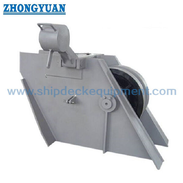
Roller Type Anchor Chain Stopper for 42–132 mm Chain | CB/T 3844-2000
Product Details:
| Place of Origin: | China |
| Brand Name: | Zhongyuan Marine Equipmen |
| Certification: | CCS, NK, BV, ABS, DNV, LR, KR, IRS, RS, RINA, CRS, Makers Test Certificate |
| Model Number: | Standard or Customized |
Payment & Shipping Terms:
| Minimum Order Quantity: | 1 Unit |
|---|---|
| Price: | Based on quotation |
| Packaging Details: | Export standard pallet or customized packing |
| Delivery Time: | Based on project requirements |
| Payment Terms: | T/T, L/C |
| Supply Ability: | Customized production based on project requirements |
|
Detail Information |
|||
| Technical Standard: | GB/T 3844-2000 | Type: | Roller Lever Type |
|---|---|---|---|
| Chain Size: | 42-132mm | Materials: | Mild Steel, C-Mn Steel, Stainless Steel, Casting Steel, Nodular Cast Iron, Steel Forging |
| Classification Certificates: | CCS, NK, BV, ABS, DNV, LR, KR, IRS, RS, RINA | Surface Treatment: | Sandblasting To S2.5 + One Layer Of Epoxy Shop Primer, Galvanized, Polished, Customized Surface Treatment Available. |
| Highlight: | roller lever chain stopper,Marine roller lever chain stopper,GB/T 3844-2000 Ship Mooring Equipment |
||
Product Description
Roller Type Anchor Chain Stopper for 42–132 mm Chain | CB/T 3844-2000
Product Overview
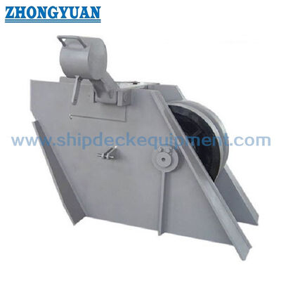
The CB/T 3844-2000 roller-type anchor chain stopper is a deck-installed chain-holding device used in ship anchoring arrangements to secure the anchor chain and transfer chain forces into the ship structure while reducing the static holding load carried by the windlass. It is normally installed in the anchor-chain line between the anchor windlass and hawse pipe.
This page covers nominal sizes 44–132 for 42–132 mm Grade 1, Grade 2 and Grade 3 anchor chains under CB/T 3844-2000. The 2000 revision uses a welded steel-plate body extended to the deck for direct welding and reinforces the side plates at the stopper-blade thrust area. Final chain-stopper height, chain entry / exit angle and chain-line alignment should be checked against the vessel arrangement and approved installation drawing.
Quick Specifications
• Product type: roller-type anchor chain stopper → secures the anchor chain in the anchoring line and reduces the holding load carried by the windlass.
• Technical standard: CB/T 3844-2000 → current Chinese marine industry standard for roller-type cable stoppers; applicable to Grade 1, 2 and 3 anchor chains from 42 to 132 mm.
• Chain diameter range: 42–132 mm through nominal sizes 44–132 → select the nominal size from the actual anchor-chain diameter and vessel drawing.
• Load verification: CB/T 3844-2000 includes strength-check guidance and specified test loads → any 80% of chain minimum breaking load statement should be treated as a design / verification basis, not as product SWL.
• Stopper blade and roller shaft: the standard specifies component material requirements and requires the roller shaft and stopper blade to be normalized before machining → final material grade and any project substitution should be confirmed.
• Reinforced side plates: the 2000 revision strengthens the body side plates at the stopper-blade thrust area → improves local load transfer into the welded body and deck structure.
• Roller and lubrication: rotating parts are greased, and the assembled roller is required to rotate freely with accurate positioning → supports chain movement and maintenance.
• Surface protection: the original standard specifies one coat of anti-rust primer followed by bituminous coating, with grease on rotating parts → epoxy, galvanizing or other modern coating systems are project-specific alternatives.
Main Technical Parameters
|
Nominal Dia. (mm) |
Chain Dia. (mm) |
L |
B |
D |
h1 / h2 |
Weight (kg) |
|---|---|---|---|---|---|---|
| 44 | 42~44 | 1000 | 380 | 484 | 392 / 281 | 274 |
| 48 | 46~48 | 1050 | 446 | 528 | 414 / 306 | 351 |
| 52 | 50~52 | 1100 | 510 | 572 | 440 / 338 | 451 |
| 56 | 54~56 | 1150 | 556 | 600 | 460 / 354 | 536 |
| 60 | 58~60 | 1200 | 610 | 620 | 490 / 378 | 651 |
| 64 | 62~64 | 1250 | 666 | 640 | 520 / 400 | 753 |
| 68 | 66~68 | 1300 | 732 | 680 | 540 / 420 | 939 |
| 73 | 70~73 | 1350 | 800 | 730 | 580 / 460 | 1178 |
| 78 | 76~78 | 1400 | 865 | 780 | 630 / 490 | 1422 |
| 84 | 81~84 | 1460 | 940 | 840 | 670 / 530 | 1758 |
| 90 | 87~90 | 1540 | 1030 | 900 | 720 / 570 | 2171 |
| 95 | 92~95 | 1600 | 1080 | 950 | 760 / 610 | 2567 |
| 102 | 97~102 | 1680 | 1150 | 1020 | 800 / 650 | 2755 |
| 107 | 105~107 | 1750 | 1210 | 1070 | 860 / 690 | 3640 |
| 114 | 111~114 | 1820 | 1270 | 1140 | 910 / 740 | 4302 |
| 122 | 117~122 | 1880 | 1340 | 1220 | 980 / 790 | 5326 |
| 132 | 124~132 | 1960 | 1440 | 1320 | 1060 / 860 | 6244 |
Selection & Inquiry Guide
Step 1: Confirm CB/T 3844-2000 roller-type anchor chain stopper and nominal size 44–132 according to the actual anchor-chain diameter.
Step 2: Provide vessel installation position, windlass-to-hawse-pipe arrangement, chain entry angle and chain exit angle so chain-line height and alignment can be checked.
Step 3: Confirm anchor-chain grade, minimum breaking load, required design / test load basis and classification requirement. Do not convert an 80% MBL design statement into product SWL.
Step 4: Confirm component materials and any approved modern equivalents for the welded body, reinforced side plates, stopper blade, roller, roller shaft, bushes, pins and related parts.
Step 5: Confirm surface-protection system, lubrication requirement, inspection / NDE scope, maker or class certificate requirement, quantity, delivery destination and required delivery time.
Step 6: Provide GA drawing, installation drawing, reference photos or replacement sample information when the chain stopper is for a repair or retrofit project.
Structure
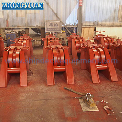
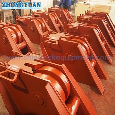
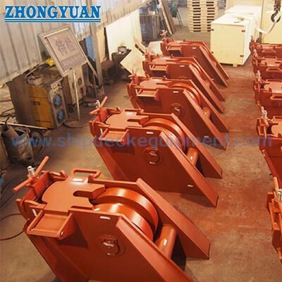
Deck-Mounted Welded Steel-Plate Body | Roller | Roller Shaft | Stopper Blade / Lever | Reinforced Side Plates at Blade Thrust Area | Bush / Pin Components | Direct Deck-Welded Base | Greased Rotating Parts
Anchor Chain Holding, Fabrication & Engineering Advantages
• Direct deck-welded body → the 2000 revision extends the steel-plate body to the deck, simplifying the standard installation interface compared with the earlier arrangement.
• Reinforced blade-thrust area → local side-plate reinforcement is concentrated where the stopper blade transfers chain force into the body.
• Controlled roller operation → the assembled roller should rotate freely and be positioned accurately; rotating parts are lubricated with grease.
• Heat-treatment control → the standard requires the roller shaft and stopper blade to be normalized before machining; any alternative material / heat-treatment route should be approved.
• Installation geometry matters → chain-stopper height and the chain entry / exit angles should align the chain correctly with the roller and stopper blade and avoid unintended side loading.
• Standard load test → the stopper is subjected to the specified test load for 5 minutes, after which the principal components should show no cracks or deformation; this test load is not the same term as SWL.
• Inspection basis → visual condition, weld quality, material-property verification and roller operation are standard checks; additional NDE and class witnessing are according to project requirement.
Custom Attributes
• Standard: CB/T 3844-2000 → current roller-type cable-stopper standard for 42–132 mm Grade 1 / 2 / 3 anchor chains.
• Type: Roller-type / roller-lever anchor chain stopper → deck-installed chain-holding equipment for ship anchoring systems.
• Nominal Size: 44–132 → select from the actual anchor-chain diameter shown in the standard table.
• Chain Size: 42–132 mm, Grade 1 / 2 / 3 → other sizes require another approved design or standard.
• Load Basis: CB/T strength check + specified test load → an 80% chain-MBL reference must not be published as product SWL.
• Stopper Blade / Roller Shaft: component-specific material and heat treatment → both are normalized before machining.
• Side-Plate Reinforcement: concentrated at the stopper-blade thrust area → supports local load transfer into the body.
• Installation Data: chain entry / exit angle and installation position required → confirm stopper height and chain-line geometry.
• Material Basis: welded steel-plate body with component-specific materials → modern equivalents require project approval.
• Surface Protection: standard primer + bituminous coating with greased rotating parts → modern coatings are project-specific.
• Certification: according to project requirement → maker / material certificates and class attendance depend on order scope.
How It Works
Anchor Chain Enters Stopper → Roller Guides Chain Line → Stopper Blade / Lever Engages Chain → Reinforced Body Transfers Load to Deck → Windlass Holding Load Is Reduced
Applications
Ship anchoring arrangement | Anchor windlass deck area | Chain stopper between windlass and hawse pipe | Forecastle deck equipment | Cargo vessels | Tankers | Bulk carriers | Container vessels | Workboats | Newbuilding and repair replacement projects
Certifications & Advantages
Certificates can be arranged according to project requirement, inspection scope, material traceability, and class society approval procedure.
Certification: CCS, NK, BV, ABS, DNV, LR, KR, IRS, RS, RINA, CRS, Makers Test Certificate.
Drawing & Photos

FAQ
Q1: What information is needed to confirm chain-stopper height?
A1: Provide installation position, chain entry / exit angles, windlass-to-hawse-pipe relationship, deck foundation and actual chain diameter so chain-line height and stopper-blade engagement can be checked.
Q2: Is 80% of anchor-chain minimum breaking load a product SWL?
A2: No. CB/T 3844-2000 uses strength-check guidance and specified test loads. An 80% MBL statement is a design / verification reference, not product SWL; final terminology follows the approved design basis.
Q3: What standard quality and inspection points should be checked?
A3: Check surface and weld condition, material compliance, free / accurate roller operation and the specified 5-minute load test. After the test, principal components should show no cracks or deformation.