


|
150–350mm Cross Bitt Bollards | Cruciform Mooring Bollards for Ship Deck
Product Details:
| Place of Origin: | China |
| Brand Name: | Zhongyuan Marine Equipmen |
| Certification: | CCS, NK, BV, ABS, DNV, LR, KR, IRS, RS, RINA, CRS, Makers Test Certificate |
| Model Number: | Standard or Customized |
| Document: | Marine Cross Bitt Bollard G...88.pdf |
Payment & Shipping Terms:
| Minimum Order Quantity: | 1 Unit |
|---|---|
| Price: | Based on quotation |
| Packaging Details: | Export standard pallet or customized packing |
| Delivery Time: | Based on project requirements |
| Payment Terms: | T/T, L/C |
| Supply Ability: | Customized production based on project requirements |
|
Detail Information |
|||
| Technical Standard: | GB 10106-88 & JIS F2804-76 | Nominal Diameters: | 150 To 350mm |
|---|---|---|---|
| Type: | Type A & Type B | Material: | Mild Steel; Stainless Steel |
| Weight: | 31 To 204kg | Surface Treatment: | Sandblasting To S2.5 + One Layer Of Epoxy Shop Primer, Polished Stainless Steel, Customized Surface Treatment Available. |
| Classification Certificates: | CCS, NK, BV, ABS, DNV-GL, LR, KR, RINA, IRS, RS, Etc. | ||
| Highlight: | Cruciform Bollards Ship Mooring Equipment,GB 10106 Ship Mooring Equipment |
||
Product Description
150–350mm Cross Bitt Bollards | Cruciform Mooring Bollards for Ship Deck
Product Overview
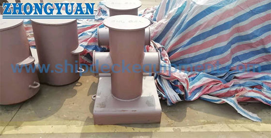
Cross bitt bollards are deck mooring fittings used to secure mooring lines on ships.
Single cross bitt cruciform bollards are designed and manufactured in accordance with GB10106-88, providing reliable mooring points for both steel wire and synthetic fiber ropes.
They provide strong and stable mooring points for both steel wire ropes and synthetic fiber ropes in marine environments.
Quick Specifications
Nominal Diameter: 150–350 mm → Defines bollard size and load capacity
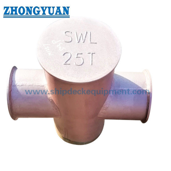
Breaking Load: 117–686 kN → Defines maximum mooring strength
Applicable Rope: Steel Wire & Fiber Rope → Ensures compatibility
Type: Type A / Type B → Defines installation method
Material: Mild Steel / Stainless Steel → Provides strength and corrosion resistance
Weight: 31–204 kg → Defines handling and installation requirement
Standard: GB10106-88 / JIS F2804-76 → Marine compliance
Surface Treatment: Sa2.5 + Coating → Improves corrosion resistance
Installation: Welded Base → Ensures structural stability
Main Technical Parameters
| Nominal Dia. |
Max. Breaking Load of Applicable Wire KN (tf) |
Steel Wire Rope |
Synthetic Fiber Rope |
Hmp Rope |
H | B | h | D | D1 | D2 | D3 | d |
Weight of Type A & B (Kg) |
|
| 150 | 117(12) | 13 | 30 | 44 | 480 | 460 | 280 | 168 | 114 | 206 | 158 | 240 | A | 31 |
| B | 33 | |||||||||||||
| 200 | 225(26) | 19.5 | 45 | 64 | 560 | 520 | 320 | 219 | 168 | 260 | 210 | 280 | A | 62 |
| B | 66 | |||||||||||||
| 250 | 382(39) | 26 | 56 | 80 | 640 | 610 | 360 | 273 | 219 | 310 | 260 | 340 | A | 98 |
| B | 105 | |||||||||||||
| 300 | 549(56) | 30 | 70 | 104 | 680 | 660 | 380 | 325 | 273 | 360 | 310 | 400 | A | 143 |
| B | 153 | |||||||||||||
| 350 | 686(70) | 34.5 | 77 | 120 | 720 | 720 | 420 | 351 | 273 | 400 | 314 | 440 | A | 192 |
| B | 204 | |||||||||||||
Selection Guide
Step 1 – Select Nominal Diameter → 150–350 mm based on mooring load
Step 2 – Confirm Breaking Load → 117–686 kN for required strength
Step 3 – Select Rope Type → Steel wire or fiber rope
Step 4 – Select Type → Type A (deck weld) or Type B (liner weld)
Step 5 – Confirm Installation → Based on deck structure
Step 6 – Select Material → Mild steel or stainless steel
Structure & Components
Cross arms | Vertical post | Base plate | Welded structure
Custom Attributes
Diameter: 150–350 mm → Defines size
Load Capacity: up to 686 kN → Defines mooring strength
Rope Compatibility: Wire & Fiber → Multi-purpose use
Installation: Welded → Structural stability
Material: Steel / Stainless → Durability
Surface: Coated or polished → Corrosion resistance
Standard: GB10106 → Compliance
Certification: CCS, NK, BV, ABS, DNV, LR, KR, IRS, RS, RINA, CRS, Makers Test Certificate
Custom Configuration & Inquiry Guide
Please provide vessel type, required load, rope type, and installation preference.
How It Works
Mooring lines are wrapped around the cross arms of the bitt, allowing secure fixation of ropes. The cruciform design distributes load evenly to ensure safe mooring.
Applications
Ship mooring | Port berthing | Offshore vessels | Tug boats
Certifications & Advantages
Certification: CCS, NK, BV, ABS, DNV, LR, KR, IRS, RS, RINA, CRS, Makers Test Certificate; simple structure, high strength, reliable mooring performance, easy installation.
Drawing & Photos
General arrangement drawing | Installation details | Product photos
![]()
![]()
![]()
Ordering
MOQ: 1 Unit | Delivery Time: 30–60 Days | Customization: Available
FAQ
Q1: What is the difference between Type A and Type B cross bitt bollards?
A:
- Type A
→ Welded directly onto the ship deck
→ Simpler installation
→ Suitable for standard deck structures - Type B
→ Welded onto a deck liner or foundation plate
→ Provides additional structural support
→ Suitable for higher load requirements or reinforced deck areas
Q2: What installation conditions require Type B instead of Type A?
A: Type B is typically used when higher loads are involved or when the deck requires reinforcement through a liner or base plate to ensure structural safety.
Q3: How to select the correct cross bitt size?
A:
Selection should be based on the required mooring load (kN) and rope diameter, following these guidelines:
- Step 1 – Determine mooring load
→ Select bollard size based on required mooring load and rope diameter. - The bollard breaking load should be selected with sufficient safety margin above the maximum expected mooring force, typically in the range of 1.5–2.0 depending on design conditions and classification society requirements.
- Step 2 – Match rope diameter
→ Ensure the bollard size is compatible with:- Steel wire rope diameter
- Synthetic fiber rope diameter
- Step 3 – Select nominal diameter
Typical reference:- 150–200 mm → small vessels
- 200–300 mm → medium vessels
- 300–350 mm → large vessels
- Step 4 – Confirm installation type
→ Type A (direct weld) or Type B (reinforced base)