


 |
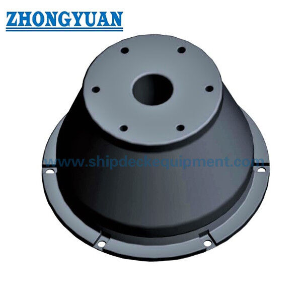
Super Cone Rubber Fender for Ports and Marine Terminals
Product Details:
| Place of Origin: | China |
| Brand Name: | Zhongyuan Marine Equipmen |
| Certification: | CCS, NK, BV, ABS, DNV, LR, KR, IRS, RS, RINA, CRS, Makers Test Certificate |
| Model Number: | Standard or Customized |
Payment & Shipping Terms:
| Minimum Order Quantity: | 1 Unit |
|---|---|
| Price: | Based on quotation |
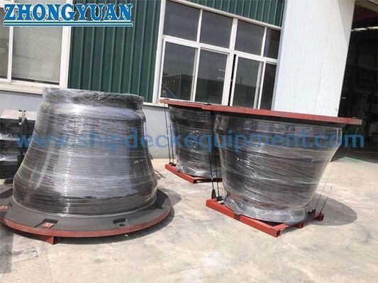
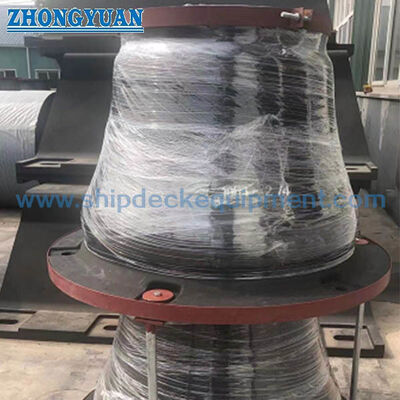
| Packaging Details: | Export standard pallet or customized packing |
| Delivery Time: | Based on project requirements |
| Payment Terms: | T/T, L/C |
| Supply Ability: | Customized production based on project requirements |
|
Detail Information |
|||
| Suitable For: | Terminals That Require Low Reaction Force And High Energy Absorption | Used In: | Large-scale Terminals Such As Oil Terminals And Container Terminals, And Overseas Development And Berthing |
|---|---|---|---|
| Certification: | CCS, BV, ABS And SGS | ||
| Highlight: | Cone rubber fenders for boats,SGS cone rubber fenders,OEM cone rubber fenders |
||
Product Description
Super Cone Rubber Fender for Ports and Marine Terminals
Product Overview
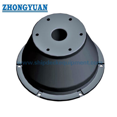
Super Cone Rubber Fender for Ports and Marine Terminals is a fixed quay fender with a conical rubber body designed for axial compression in a berth-side fender system. The dimensional series covers nominal heights from 500 to 1,800 mm. Performance data is arranged in four reaction grades—RSS, RH, RO and RL—so the fender can be selected against the required energy absorption and allowable reaction for the berth and vessel interface. The series uses 70% design deflection, with 72.5% listed as the maximum compression condition.
A complete cone fender system can combine the rubber element with a frontal panel, facing pads, anchors and restraint/support chains as required by the project. This makes the product suitable for terminal designs where energy absorption, reaction force, hull contact pressure, panel geometry and installation clearance must be considered together rather than treating the rubber unit as an isolated component.
Quick Specifications
- Product type: Fixed cone-shaped marine rubber fender
- Supplied height range: 500–1,800 mm
- Design deflection: 70%
- Maximum listed compression condition: 72.5%
- Performance grades: RSS | RH | RO | RL
- Performance tolerance: ±10%
- Typical system arrangement: Rubber unit | closed-box steel front panel | UHMW-PE facing pads | anchors | hot-dip galvanized chain assemblies
Rubber material control: tensile strength ≥16 MPa, elongation at break ≥400%, hardness ≤78 Shore A and compression set ≤30%. Tear resistance, ozone resistance, seawater resistance, abrasion resistance and rubber-to-steel bond strength are controlled using the applicable ISO test methods and project acceptance criteria.
Structure & Fender System Configuration
Cone rubber element | fabricated closed-box steel front panel | bolted UHMW-PE facing pads | anchor/embedded parts | weight, tension and shear chains where required. The front panel is specified as Q355B structural steel to GB/T 1591-2018 or an approved equivalent. The welded closed-box structure is subjected to a tightness test to verify sealing against water ingress. Marine corrosion protection is based on surface preparation to Sa 2½ and a protective paint system selected in accordance with ISO 12944 for the project exposure category.
Facing pads are specified as virgin, black, UV-stabilized UHMW-PE and are mechanically bolted to the vessel-contact face of the steel panel. A typical pad thickness of 50–80 mm is used for medium-to-heavy marine service, with final thickness selected for wear allowance, contact pressure and project duty. Hot-dip galvanized open-link or stud-link chain assemblies may be used for panel weight support, tension control and shear restraint. Chain grade and diameter are selected from the calculated design load and required minimum breaking load; matched shackles, tensioners, brackets and anchors are sized to the same project basis.
Main Technical Parameters
|
Item |
Range / Configuration |
Selection Meaning |
|---|---|---|
| Nominal height H | 500–1,800 mm | Selects the fender size and available compression stroke |
| Design deflection | 70% | Primary condition for design performance selection |
| Maximum listed compression | 72.5% | Additional source-listed performance condition |
| Reaction grades | RSS | RH | RO | RL | Provides different reaction/energy combinations |
| Performance tolerance | ±10% | Apply with the agreed project/test specification |
| System interfaces | Panel | pads | anchors | chains | Project-specific system integration |
Supplied Series – Main Dimensions
|
Type |
H (mm) |
D1 (mm) |
D2 (mm) |
D3 (mm) |
D4 (mm) |
Holes |
|---|---|---|---|---|---|---|
| C500H | 500 | 750 | 675 | 325 | 425 | 4 |
| C600H | 600 | 900 | 810 | 390 | 510 | 6 |
| C700H | 700 | 1050 | 945 | 455 | 595 | 6 |
| C800H | 800 | 1200 | 1080 | 520 | 680 | 6 |
| C900H | 900 | 1350 | 1215 | 585 | 765 | 6 |
| C1000H | 1000 | 1500 | 1350 | 650 | 850 | 6 |
| C1100H | 1100 | 1650 | 1485 | 715 | 935 | 6 |
| C1150H | 1150 | 1725 | 1550 | 750 | 998 | 6 |
| C1200H | 1200 | 1800 | 1620 | 780 | 1020 | 8 |
| C1300H | 1300 | 1950 | 1755 | 845 | 1105 | 8 |
| C1400H | 1400 | 2100 | 1890 | 930 | 1190 | 8 |
| C1600H | 1600 | 2400 | 2160 | 1060 | 1360 | 8 |
| C1800H | 1800 | 2700 | 2430 | 1190 | 1530 | 8 |
Performance at 70% Design Deflection
The following values show the performance series at 70% design deflection. Reaction force is shown in kN and energy absorption in kJ (1 kJ = 1 kN·m). Performance tolerance is ±10%.
|
Type |
RSS Reaction (kN) |
RSS Energy (kJ) |
RH Reaction (kN) |
RH Energy (kJ) |
|---|---|---|---|---|
| C500H | 335 | 79 | 268 | 63 |
| C600H | 480 | 157 | 382 | 127 |
| C700H | 652 | 235 | 522 | 181 |
| C800H | 862 | 368 | 706 | 294 |
| C900H | 1078 | 494 | 862 | 399 |
| C1000H | 1339 | 669 | 1078 | 541 |
| C1100H | 1430 | 830 | 1146 | 650 |
| C1150H | 1764 | 1029 | 1392 | 882 |
| C1200H | 1746 | 1103 | 1396 | 882 |
| C1300H | 2125 | 1585 | 1705 | 1310 |
| C1400H | 2255 | 1686 | 1804 | 1349 |
| C1600H | 3024 | 2419 | 2268 | 1935 |
| C1800H | 3750 | 3538 | 3000 | 2830 |
|
Type |
RO Reaction (kN) |
RO Energy (kJ) |
RL Reaction (kN) |
RL Energy (kJ) |
|---|---|---|---|---|
| C500H | 200 | 47 | 165 | 37 |
| C600H | 283 | 94 | 225 | 75 |
| C700H | 384 | 150 | 308 | 120 |
| C800H | 502 | 224 | 402 | 179 |
| C900H | 635 | 306 | 508 | 255 |
| C1000H | 784 | 437 | 628 | 350 |
| C1100H | 927 | 495 | 800 | 408 |
| C1150H | 1038 | 666 | 830 | 532 |
| C1200H | 1106 | 705 | 890 | 560 |
| C1300H | 1320 | 1043 | 1125 | 750 |
| C1400H | 1443 | 1079 | 1150 | 860 |
| C1600H | 1814 | 1548 | 1413 | 1234 |
| C1800H | 2401 | 2264 | 1912 | 1804 |
Step 1 – Define the berthing requirement: Provide vessel type and size range, berth arrangement, design berthing energy, allowable reaction/hull pressure, fender spacing and the governing project design basis.
Step 2 – Select fender height and performance grade: Use the 70% design-performance table to match required energy absorption and reaction. Do not select only by nominal height.
Step 3 – Define the frontal system: Confirm panel dimensions, facing-pad arrangement, chain configuration, anchor/embedded parts and available installation clearance.
Step 4 – Confirm operating and verification conditions: State the project temperature range, berthing velocity/angle assumptions, required performance verification, inspection frequency, third-party witnessing and documentation requirements.
Key Engineering Advantages
- Four listed reaction grades provide a practical way to balance required energy absorption against allowable reaction within the supplied series.
- The conical body is suited to large axial compression and provides a stable geometry for fender systems that may also experience shear or angled vessel contact.
- The product can be integrated with a frontal panel and facing-pad system where a larger contact area or controlled hull pressure is required.
- A broad dimensional series supports selection across different berth layouts without creating separate thin pages for each nominal height.
Installation & System Interface
The standard installation interface places the cone fender between the berth structure and the fabricated closed-box steel front panel through bolted flange connections. UHMW-PE facing pads are bolted to the vessel-contact face of the panel. For new reinforced-concrete berth structures, cast-in anchors can be positioned with an installation template and integrated with the reinforcement. For existing structures, suitable post-installed anchors may be used subject to structural verification.
Final anchor locations, embedment, concrete reinforcement, edge distances, bracket positions and chain geometry are determined from the project loads and the approved GA/anchor layout. The project drawing should also confirm fender orientation, panel clearance and the available compression envelope. A typical current cone-fender arrangement places the larger foot flange toward the supporting structure and the smaller head flange toward the front panel, unless the approved project design requires otherwise.
Inspection & Documentation
Baseline quality verification includes visual and dimensional inspection; rubber material-property testing using applicable ISO methods; and full-scale compression performance verification against the specified reaction-force and energy-absorption values. For complete fender systems, inspection can also include front-panel welding and closed-box tightness testing, surface-preparation/coating and dry-film-thickness checks, hot-dip galvanized chain/accessory inspection, and relevant proof-load or material certificates where specified. Sampling, correction conditions, acceptance criteria and third-party witnessing are defined by the purchase specification and the applicable project guidance, including PIANC Fender Guidelines 2024 where required.
Third-party witnessing, class involvement, material certificates, performance test reports and maker documentation should be specified separately where required; they are not assumed to be included with every order.
Applications
Container & bulk terminals | oil & gas terminals | general cargo berths | ferry & RoRo terminals | cruise terminals | other fixed berth fender systems requiring project-specific energy and reaction selection
Drawing & Photos

FAQ
Q1 How is the correct Super Cone Rubber Fender grade selected?
A1 Selection should start from the required berthing energy and the allowable fender reaction, then check the nominal height, available deflection, vessel hull pressure, panel arrangement and berth geometry. The grade should not be chosen from nominal size alone.
Q2 Can the cone fender be supplied as a complete system with a front panel and chains?
A2 A cone fender can be configured with a frontal panel, facing pads, anchors and support/restraint chains to suit the project. The final component sizes, materials and connection details must be confirmed for the berth design.
Q3 How can the reaction force and energy absorption be verified?
A3 Performance can be verified by an agreed compression test procedure using calibrated measurement equipment and project-defined acceptance criteria. The required sampling level, test conditions, documentation and any third-party witnessing should be stated in the purchase specification.