


 |
Cylindrical Rubber Fender for Tugboats and Marine Terminals
Product Details:
| Place of Origin: | China |
| Brand Name: | Zhongyuan Marine Equipmen |
| Certification: | CCS, NK, BV, ABS, DNV, LR, KR, IRS, RS, RINA, CRS, Makers Test Certificate |
| Model Number: | Standard or Customized |
Payment & Shipping Terms:
| Minimum Order Quantity: | 1 Unit |
|---|---|
| Price: | Based on quotation |
| Packaging Details: | Export standard pallet or customized packing |
| Delivery Time: | Based on project requirements |
| Payment Terms: | T/T, L/C |
| Supply Ability: | Customized production based on project requirements |
|
Detail Information |
|||
| Type: | CY | Applicable To: | All Kinds Ship And Dock Side |
|---|---|---|---|
| Certification: | CCS, BV, ABS And SGS | ||
| Highlight: | CY boat rubber fender,ABS boat rubber fender,rubber marine dock fenders |
||
Product Description
Cylindrical Rubber Fender for Tugboats and Marine Terminals
Product Overview
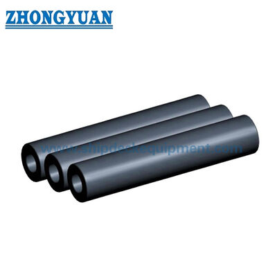
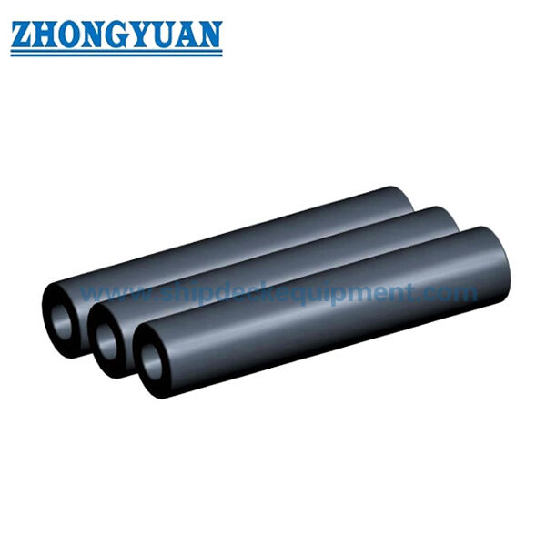
Cylindrical Rubber Fender for Tugboats and Marine Terminals is a simple hollow cylindrical solid-rubber fender used on quays, docks, tugboats, push boats and other vessel-contact locations. It can be installed by a central chain or bar, by suspension, or with machined circumferential grooves for straps / chains where required.
The supplied standard performance series covers outside diameters from 150 to 1,200 mm at 1,000 mm reference length, with 50% design compression data. A separate tugboat / push-boat manufacturing table confirms long cylindrical lengths up to 20,000 mm for many grooved and non-grooved configurations.
Quick Specifications
- Product type: Hollow cylindrical solid rubber fender
- Supplied outside diameter range in standard performance table: 150–1,200 mm
- Typical ID/OD ratio in standard series: approximately 0.5
- Published performance point: 50% design compression
- Published reference length for performance table: 1,000 mm
- Long manufactured lengths: up to 20,000 mm for many listed configurations
- Available installation forms: plain cylindrical | grooved cylindrical | vessel bow/stern cylindrical arrangement
Structure & Configuration
Hollow cylindrical rubber body | central bore for suspension / fixing | optional circumferential installation grooves | optional tapered ends and project-specific vessel-side fixing arrangement.
For cylindrical products, the supplied manufacturing information supports automatic extrusion/winding, layer compaction, integral vulcanization and machining of installation grooves where required. This process description is not generalized to the moulded D, W or other profile-fender families.
Main Technical Parameters
Standard Series – Dimensions
|
Type |
Outer Diameter D (mm) |
Inner Diameter d (mm) |
Length L (mm) |
|---|---|---|---|
| CY150 × L | 150 | 75 | 500–20,000 |
| CY200 × L | 200 | 100 | 500–20,000 |
| CY300 × L | 300 | 150 | 500–20,000 |
| CY400 × L | 400 | 200 | 500–20,000 |
| CY500 × L | 500 | 250 | 500–20,000 |
| CY600 × L | 600 | 300 | 500–20,000 |
| CY700 × L | 700 | 350 | 500–20,000 |
| CY800 × L | 800 | 400 | 500–20,000 |
| CY900 × L | 900 | 450 | 500–20,000 |
| CY1000 × L | 1000 | 500 | 500–20,000 |
| CY1100 × L | 1100 | 550 | 500–20,000 |
| CY1200 × L | 1200 | 600 | 500–20,000 |
Published Performance at 50% Compression – 1,000 mm Reference Length
|
Type |
Reaction Force (kN) |
Energy Absorption (kJ) |
Tolerance |
|---|---|---|---|
| CY150 × 1000 | 44.1 | 1.5 | ±10% |
| CY200 × 1000 | 59.8 | 2.6 | ±10% |
| CY250 × 1000 | 74.6 | 4.1 | ±10% |
| CY300 × 1000 | 89.3 | 5.9 | ±10% |
| CY400 × 1000 | 118.7 | 10.4 | ±10% |
| CY500 × 1000 | 148.1 | 16.1 | ±10% |
| CY600 × 1000 | 178.5 | 23.5 | ±10% |
| CY700 × 1000 | 208 | 31.4 | ±10% |
| CY800 × 1000 | 237.4 | 41.2 | ±10% |
| CY900 × 1000 | 267.8 | 52.0 | ±10% |
| CY1000 × 1000 | 297.2 | 63.8 | ±10% |
| CY1100 × 1000 | 331 | 77.2 | ±10% |
| CY1200 × 1000 | 363 | 95.2 | ±10% |
Grooved / Long-Length Manufacturing Reference
|
Configuration |
Size |
ID (mm) |
OD (mm) |
Maximum Listed Length |
|---|---|---|---|---|
| Grooved | Ø200 × Ø100 × L | 100 | 200 | ≤15,000 |
| Grooved | Ø300 × Ø150 × L | 150 | 300 | ≤20,000 |
| Grooved | Ø400 × Ø200 × L | 200 | 400 | ≤20,000 |
| Grooved | Ø500 × Ø220 / Ø250 × L | 220 / 250 | 500 | ≤20,000 |
| Grooved | Ø600 × Ø300 × L | 300 | 600 | ≤20,000 |
| Grooved | Ø700 × Ø350 × L | 350 | 700 | ≤20,000 |
| Grooved | Ø750 × Ø350 × L | 350 | 750 | ≤20,000 |
| Grooved | Ø800 × Ø400 × L | 400 | 800 | ≤20,000 |
| Grooved | Ø900 × Ø450 × L | 450 | 900 | ≤20,000 |
| Grooved | Ø1000 × Ø500 × L | 500 | 1000 | ≤20,000 |
| Grooved | Ø1100 × Ø550 × L | 550 | 1100 | ≤20,000 |
| Grooved | Ø1200 × Ø600 × L | 600 | 1200 | ≤20,000 |
Selection & Inquiry Guide
Step 1 – Confirm installation location: tug/push-boat bow or side, quay, dock, suspended position or replacement installation.
Step 2 – Select OD, ID and total length from required energy/reaction, available space and fixing method.
Step 3 – Confirm plain or grooved configuration, groove quantity/position, chain or strap arrangement and end details.
Step 4 – For performance-based selection, state whether the 1,000 mm / 50% catalogue values are the acceptance basis or whether a project-specific full-scale test is required.
Step 5 – Confirm quantity, drawing, inspection/documentation scope and delivery destination.
Key Engineering Advantages
- Simple circular geometry allows suspension, central-bar or vessel-mounted arrangements with relatively uncomplicated replacement.
- Long-length manufacturing and machined installation grooves support tugboat and push-boat bow/stern arrangements.
- The 50% performance table provides direct reaction and energy values for the supplied OD series at 1,000 mm reference length.
- Different OD/ID combinations can be engineered where the standard catalogue series does not match the existing installation.
Installation & System Interface
Cylindrical fenders may be suspended through the center bore, retained by chains/rods, or installed with circumferential grooves and straps/chains. For tugboat bow/stern arrangements, groove geometry, strap/chain load, end transitions and hull support details must be coordinated with the vessel structure.
Inspection & Documentation
Baseline quality control includes visual inspection, dimensional verification and rubber physical-property testing. Where a quantified reaction-force / energy-absorption table is part of the agreed product specification, full-scale compression testing can be included in the project ITP to verify the guaranteed performance under defined test conditions.
PIANC Fender Guidelines 2024 (MarCom WG211) are used as the current engineering reference for fender-system design, manufacturing and testing principles. Type approval, product certification, third-party witnessing and class documentation are stated only when the corresponding scope has been agreed and documented.
Applications
Tugboats | push boats | workboats | quay walls | docks | suspended fender systems | vessel bow and stern protection | replacement cylindrical fenders
Drawing & Photos

FAQ
Q1: Why is CY900 shown with 450 mm inner diameter? — The 900/450 geometry is supported by the grooved product table and consistent international cylindrical-fender references; the isolated 350 mm entry in one source is treated as a source error.
Q2: Do the 50% performance values scale directly with length? — The published table is for 1,000 mm reference length. Project values for other lengths should be confirmed through the approved product calculation / performance basis rather than assumed without verification.
Q3: When are grooves used? — Grooves are used where straps or chains must locate and retain the fender on a vessel or support structure; groove geometry is project-specific.