


|
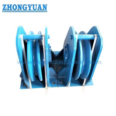
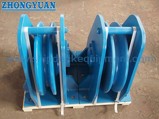
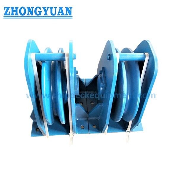
Vertical Wire Rope Sheave Block | 20–76 mm Rope Sheave Assembly
Product Details:
| Place of Origin: | China |
| Brand Name: | Zhongyuan Marine Equipmen |
| Certification: | CCS, NK, BV, ABS, DNV, LR, KR, IRS, RS, RINA, CRS, Makers Test Certificate |
| Model Number: | Standard or Customized |
Payment & Shipping Terms:
| Minimum Order Quantity: | 1 Unit |
|---|---|
| Price: | Based on quotation |
| Packaging Details: | Export standard pallet or customized packing |
| Delivery Time: | Based on project requirements |
| Payment Terms: | T/T, L/C |
| Supply Ability: | Customized production based on project requirements |
|
Detail Information |
|||
| Steel Wire Diameters: | 20mm~76mm | Material: | Cast Steel, C-Mn Steel, Alloy Steel, Mild Steel |
|---|---|---|---|
| Type: | Vertical, Stand, Horizontal, Bolted, Welded | Surface Treatment: | Sandblasting To S2.5 + 3 Layers Of Epoxy Paint, Galvanized |
| Classification Certificates: | CCS, NK, BV, ABS, DNV, LR, KR, RINA, IRS, RS, Etc | ||
| Highlight: | Corrosion Resistant Vertical Sheave,Self lubrication Vertical Sheave,Ship Towing Equipment Sheave |
||
Product Description
Vertical Wire Rope Sheave Block | 20–76 mm Rope Sheave Assembly
Product Overview
The vertical wire rope sheave block is a fixed direction-changing component used to guide a running steel wire rope through a controlled vertical plane. It is commonly installed in lifting equipment, lifting-winch reeving systems, ramp door operating winches, towing winch arrangements, engineering vessels, ferries, workboats, special-purpose ships, and dock equipment. The grooved rotating sheave supports the rope path and changes its direction while transferring the resulting rope reaction through the shaft, frame, and mounting foundation.
The product is selected as part of the complete wire-rope and winch system. Rope diameter is only the starting point; the rope construction, minimum breaking load, winch line pull, brake holding load, operating speed, duty cycle, direction-change angle, fleet angle, required sheave pitch diameter, groove profile, shaft and bearing arrangement, and installation foundation must also be confirmed. Vertical, stand/pedestal, horizontal, bolted, and welded versions can be configured to suit the equipment layout. When used in lifting equipment, the guide sheave and its supporting structure must be verified under the applicable lifting design, inspection, test, and class or statutory requirements.
Quick Specifications
- Steel wire rope range: 20 to 76 mm → covers guide-sheave arrangements for lifting winches, ramp door winches, towing winches, and other marine or dock wire-rope systems.
- Supplied sheave diameter Φ: 340 to 1120 mm → the drawing must confirm whether Φ is outside diameter or pitch diameter before the final D/d ratio is checked.
- Main envelope range: A 280 to 1350 mm, B 390 to 1250 mm, H 220 to 720 mm → useful for preliminary equipment-space, access, and foundation planning.
- Typical applications: lifting equipment, lifting winches, ramp door operating winches, towing winches, and dockside wire-rope systems → the final model must match the actual rope path and load case.
- Configuration options: vertical, stand/pedestal, horizontal, bolted, or welded → select according to rope direction, change-of-direction angle, maintenance access, and supporting structure.
- Material and finish options: cast steel, C-Mn steel, alloy steel, or mild steel with Sa 2½ blasting and epoxy shop primer, polishing, galvanizing, or project coating → exact grade and finish follow the duty and environment.
- Operating focus: controlled wire-rope guidance, suitable groove profile, free sheave rotation, and accessible inspection → supports predictable rope routing and reduced sliding contact at the direction-change point.
- Certificates: maker documentation or class-related certification can be arranged according to project requirement, intended service, and agreed inspection scope.
Main Technical Parameters
| Steel Wire Rope Dia. (mm) |
A (mm) |
B (mm) |
H (mm) |
Φ (mm) |
| 20 | 280 | 390 | 220 | 340 |
| 25 | 330 | 480 | 265 | 425 |
| 32 | 406 | 590 | 340 | 520 |
| 38 | 362 | 690 | 380 | 600 |
| 44 | 560 | 815 | 450 | 710 |
| 52 | 610 | 1010 | 570 | 880 |
| 60 | 760 | 1100 | 600 | 930 |
| 68 | 920 | 1150 | 650 | 956 |
| 76 | 1350 | 1250 | 720 | 1120 |
Selection & Inquiry Guide
Step 1: Confirm the application and rope route: lifting equipment, lifting winch, ramp door operating winch, towing winch, dock winch, vessel type, installation position, incoming rope direction, outgoing rope direction, and required change-of-direction angle.
Step 2: Provide the steel wire rope data: nominal diameter, construction, core type, lay direction, minimum breaking load, rope manufacturer, and recommended minimum sheave pitch diameter.
Step 3: Confirm the system duty and design load: maximum line pull or design rope tension, brake holding load, operating speed, dynamic factor, duty cycle, lifting load case or ramp door operating force where applicable, and expected shock or transient loading.
Step 4: Select the arrangement: vertical, stand/pedestal, horizontal, bolted, or welded; provide the equipment and foundation drawing, available space, maintenance clearance, rope fleet angle, and intended load direction.
Step 5: Confirm material and rotating parts: sheave and frame grade, groove-hardening requirement, shaft material, bearing or bushing type, sealing, lubrication method, and replaceable wear parts.
Step 6: Confirm surface treatment, quantity, applicable lifting or marine standard, certificate and inspection scope, destination, required delivery time, and the approved GA or reference photo before production.
Structure
Grooved steel sheave | Shaft and retaining arrangement | Bearing or bushing system | Vertical support frame | Bolted or welded mounting base | Lubrication and sealing points as specified | Marine coating or project finish
Wire Rope Guidance, Installation & Quality Advantages
- The rotating grooved sheave guides the running wire rope and changes its direction through rolling contact, helping avoid direct sliding over a fixed steel edge when the rope is correctly aligned.
- Sheave size and groove geometry should match the actual rope construction. The final D/d ratio must use the groove pitch diameter, not an unconfirmed outside diameter.
- The guide position should be coordinated with the winch drum, adjacent sheaves, ramp door mechanism, lifting reeving, or towing lead so that the fleet angle and side lead remain within the equipment and rope supplier’s permitted arrangement.
- Rope tension acting through a direction change creates a combined reaction at the shaft, frame, mounting bolts or welds, and supporting structure. The reaction depends on both rope tension and the included rope angle.
- For lifting-equipment service, the sheave block, foundation, safety factors, material traceability, inspection, proof testing, and marking must be verified as part of the applicable lifting system; rope diameter alone does not establish a lifting rating.
- Groove hardening, self-lubricating bushings, or vibration-damping elements can be specified when required, but the method, material, hardness, lubrication arrangement, and inspection criteria must be confirmed before quotation.
- Accessible shaft, bearing or bushing, groove, and rope-contact areas support routine inspection, lubrication, wear measurement, and replacement planning.
Custom Attributes
- Product Function: Wire-rope guide and direction-changing sheave → used with a winch or reeving system to control the rope path and redirect the running rope.
- Rope Diameter: 20 / 25 / 32 / 38 / 44 / 52 / 60 / 68 / 76 mm → preliminary model selection follows the supplied dimensional series.
- Typical Service: Lifting winch / ramp door winch / towing winch / dock winch → each application requires its own load case, rope route, duty, and approval review.
- Configuration: Vertical / stand / horizontal, with bolted or welded mounting → choose according to rope lead, equipment layout, maintenance access, and foundation design.
- Material: Cast steel / C-Mn steel / alloy steel / mild steel → exact grade, traceability, heat treatment, and weldability are to be confirmed.
- Groove Surface: Machined and optionally hardened → groove profile, contact radius, surface finish, and hardness requirement should match the selected rope.
- Bearing & Lubrication: To be confirmed → specify rolling bearing, plain bushing, self-lubricating bushing, seals, grease points, and maintenance interval as required.
- Load Basis: To be confirmed → model selection requires design rope tension, change-of-direction angle, dynamic factor, duty, and foundation reaction; rope diameter is not a load rating.
- Certificate Requirement: According to project scope → maker certificate, material certificate, inspection report, lifting-related documentation, or class involvement should be agreed before order.
How It Works
Wire rope leaves the winch drum or preceding sheave → Rope enters the machined groove → The rotating sheave guides the rope and changes its direction → Shaft and frame transfer the resulting reaction to the mounting foundation → Rope continues toward the lifting reeving, ramp door mechanism, towing lead, or other working point
Applications
Marine and industrial lifting equipment | Lifting winches | Ramp door operating winches | Ro-Ro ferries and landing craft | Towing winches and towing-wire routing | Engineering vessels | Workboats and special-purpose ships | Dock and shipyard winch systems
Certifications & Advantages
Certificates and inspection can be arranged according to project requirement, material traceability, agreed test scope, and classification society approval procedure. Availability and witnessing requirements should be confirmed before quotation.
Certification: CCS, NK, BV, ABS, DNV, LR, KR, IRS, RS, RINA, CRS, Makers Test Certificate.
Drawing & Photos

FAQ
Q1: How is the correct guide sheave model selected?
A1: Start with rope diameter, but also confirm rope construction, minimum breaking load, design rope tension, winch line pull, brake holding load, operating speed, deflection angle, duty cycle, groove profile, pitch diameter, and mounting reactions. The dimensional table alone is not a load-capacity table.
Q2: Can one guide sheave model be used for lifting, ramp door, and towing systems?
A2: Only when the actual design has been checked for that service. These applications can have different rope tensions, dynamic factors, duty cycles, safety factors, inspection requirements, and foundation reactions. A model should not be transferred between applications based only on rope diameter.
Q3: What is the difference between bolted and welded installation?
A3: A bolted base can support removal and maintenance when the foundation, fasteners, and preload are correctly designed. A welded base provides a permanent connection but requires confirmed material compatibility, weld details, access, inspection, and supporting-structure reinforcement.