


|
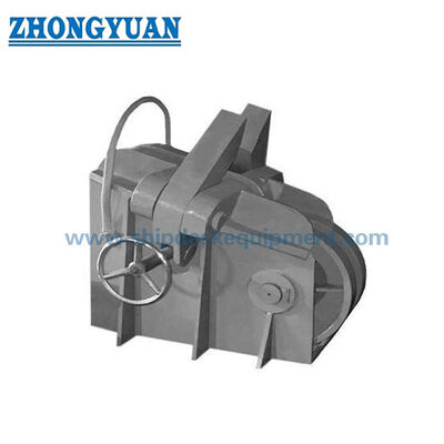
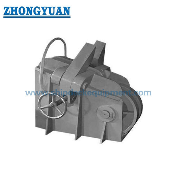
Screw-Type Anchor Chain Stopper for 50–102 mm Chain | CB/T 178-1996 Type B
Product Details:
| Place of Origin: | China |
| Brand Name: | Zhongyuan Marine Equipmen |
| Certification: | CCS, NK, BV, ABS, DNV, LR, KR, IRS, RS, RINA, CRS, Makers Test Certificate |
| Model Number: | Standard or Customized |
Payment & Shipping Terms:
| Minimum Order Quantity: | 1 Unit |
|---|---|
| Price: | Based on quotation |
| Packaging Details: | Export standard pallet or customized packing |
| Delivery Time: | Based on project requirements |
| Payment Terms: | T/T, L/C |
| Supply Ability: | Customized production based on project requirements |
|
Detail Information |
|||
| Technical Standard: | GB/T 178-96 | Type: | Screw Type B |
|---|---|---|---|
| Chain Size: | 50-102mm | Materials: | Mild Steel, C-Mn Steel, Stainless Steel, Casting Steel, Nodular Cast Iron, Steel Forging |
| Surface Treatment: | Sandblasting To S2.5 + One Layer Of Epoxy Shop Primer, Galvanized, Polished, Customized Surface Treatment Available. | Classification Certificates: | CCS, NK, BV, ABS, DNV, LR, KR, IRS, RS, RINA |
| Highlight: | 50mm marine chain stopper,cb/t 178 type b marine chain stopper,cb/t 178 type b anchor chain stopper |
||
Product Description
Screw-Type Anchor Chain Stopper for 50–102 mm Chain | CB/T 178-1996 Type B
Product Overview
The CB/T 178-1996 Type B screw type anchor chain stopper is a deck-installed anchoring component used to secure large stud-link anchor chains and transfer chain load into the vessel structure when the stopper is engaged. The Type B range covers anchor chain diameters from 50 mm to 102 mm and is normally associated with higher-strength U3 anchor chain applications.
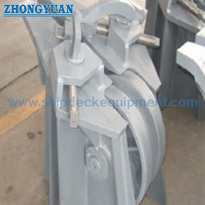
The assembly combines a screw-operated stopping mechanism, cast steel load-bearing parts, carbon-steel fabricated parts, and a front roller that supports smoother chain movement and reduces sliding contact during anchor handling. Final selection should be coordinated with the anchor windlass arrangement, chain grade, chain lead, deck foundation, welding details, inspection scope, and the applicable classification society rules.
Quick Specifications
- Product type: Screw type anchor chain stopper → secures the anchor chain and relieves the anchor windlass from sustained chain load when properly engaged.
- Standard and type: CB/T 178-1996 Type B → public standard listings identify the overall screw chain stopper range as 22-102 mm, with Type B covering 50-102 mm.
- Anchor chain range: 50-102 mm → eleven standard size groups for larger ship anchor chain arrangements.
- Chain grade basis: typically U3 for Type B → any U2 application should be confirmed against the vessel drawing, official standard, and class requirement.
- Reference load basis: 80% of the corresponding U3 anchor chain breaking load as supplied → this is a design / verification basis, not a declared product SWL.
- Front roller: one roller ahead of the stopping mechanism → supports chain movement and reduces direct sliding friction through the stopper area.
- Installation: welded directly to the reinforced deck or mounted on a welded foundation → deck strength, weld details, and alignment must be confirmed by the shipyard or design office.
- Reference surface preparation: Sa 2.5 blasting + epoxy shop primer → final coating system follows the vessel paint specification and order scope.
Main Technical Parameters
| Anchor Chain Size |
B | B1 | B2 | H | H1 | H2 | H3 | H4 | d | d1 | d2 | |
| 50~52 | 1020 | 333 | 150 | 1130 | 450 | 310 | 180 | 755 | T26 X 1 4/2 | 400 | 35 | |
| 54~ 56 | 1090 | 335 | 150 | 1210 | 485 | 330 | 205 | 746 | T55 X 14 /2 | 400 | 35 | |
| 58~60 | 170 | 371 | 150 | 1270 | 528 | 350 | 225 | 740 | T60 X 14 / 2 | 400 | 40 | |
| 62~ 64 | 1250 | 393 | 200 | 1360 | 555 | 370 | 245 | 725 | T65 X 16/ 2 | 500 | 40 | |
| 66 ~ 68 | l330 | 415 | 200 | 1430 | 580 | 390 | 265 | 715 | T70 X l 6/ 2 | 500 | 45 | |
| 70~73 | 1410 | 441 | 200 | 1510 | 605 | 415 | 285 | 700 | T70 X 16/ 2 | 500 | 45 | |
| 76~78 | 1500 | 463 | 250 | 1590 | 630 | 440 | 300 | 690 | T75 X J 6/ 2 | 500 | 50 | |
| 81 ~ 84 | 1600 | 485 | 250 | 1630 | 665 | ·470 | 325 | 680 | T 80 X 16/ 2 | 630 | 50 | |
| 87~ 90 | 1710 | 507 | 250 | 1670 | 700 | 500 | 350 | 670 | T85 X 18 / 2 | 630 | 55 | |
| 92~ 95 | 1820 | 529 | 300 | 1710 | 735 | 525 | 365 | 660 | T90X 18 / 2 | 630 | 55 | |
| 97~102 | 1940 | 551 | 300 | 1750 | 770 | 560 | 390 | 650 | T90 X 18 / 2 | 630 | 55 | |
| Anchor Chain Size |
L | L1 | L2 | L3 | L4 | L5 | L6 | D | t | t1 | R | Weight kg |
| 50~52 | 1040 | 980 | 440 | 370 | 275 | 200 | 120 | 520 | 26 | 12 | 245 | 1700 |
| 54~56 | 1120 | 1040 | 48 0 | 390 | 305 | 200 | 120 | 560 | 26 | 12 | 255 | 1805 |
| 58~ 60 | 1180 | 1100 | 520 | 410 | 315 | 220 | 120 | 600 | 28 | 12 | 260 | 1930 |
| 62~ 64 | 1270 | 1175 | 560 | 430 | 345 | 220 | 160 | 640 | 30 | 16 | 275 | 1960 |
| 66~68 | 1340 | 1240 | 600 | 450 | 365 | 230 | 160 | 680 | 30 | 16 | 285 | 2180 |
| 70~73 | 1420 | 1270 | 635 | 475 | 390 | 230 | 160 | 730 | 32 | 16 | 300 | 2420 |
| 76~78 | 1500 | 1340 | 670 | 500 | 415 | 340 | 160 | 780 | 34 | 16 | 310 | 2630 |
| 81~ 84 | 1610 | 1420 | 700 | 530 | 450 | 240 | 200 | 810 | 36 | 20 | 320 | 2860 |
| 87~90 | 1700 | 1490 | 730 | 560 | 475 | 250 | 200 | 900 | 38 | 20 | 330 | 3170 |
| 92~ 95 | 1800 | 1560 | 765 | 585 | 515 | 250 | 200 | 950 | 38 | 20 | 340 | 3420 |
| 97~102 | 1890 | 1 630 | 790 | 620 | 540 | 250 | 200 | 1020 | 40 | 20 | 350 | 3798 |
Selection & Inquiry Guide
Step 1: Confirm CB/T 178-1996 Type B and the anchor chain diameter group from 50-52 mm through 97-102 mm.
Step 2: Confirm anchor chain grade, minimum breaking load, anchor windlass arrangement, chain lead direction, and whether the project requires the 80% chain breaking-load design basis.
Step 3: Confirm deck installation form: direct deck welding or welded foundation, including deck reinforcement, weld details, available space, and alignment with the chain pipe and windlass.
Step 4: Confirm the part-by-part material specification, especially cast steel load-bearing parts, carbon-steel fabricated parts, screw / nut material, roller shaft, and any heat-treatment requirement.
Step 5: Confirm surface preparation, final coating system, lubrication points, maker certificate, material traceability, class inspection, load test, and witness requirements.
Step 6: Provide quantity, vessel type, installation drawing or GA drawing, classification society, delivery destination, and required delivery time.
Structure
Cast steel load-bearing body | Screw-operated stopping mechanism | Chain-contact stopping members | Front support roller | Roller shaft and bearing / bush interface | Welded deck base or foundation | Hand-operated screw and nut assembly | Protective coating and lubrication points
Anchoring, Operation & Quality Advantages
- The screw-operated mechanism provides controlled engagement and release of the anchor chain without treating the product as a lifting device or winch.
- When engaged, the chain stopper transfers anchor-chain load through its body and foundation into the reinforced deck structure, reducing sustained load on the anchor windlass and chain wheel.
- The front roller supports the chain path and helps reduce sliding friction during heaving or paying out, especially for the larger 50-102 mm chain range.
- Cast steel and fabricated steel parts should be controlled separately for material traceability, casting quality, dimensional accuracy, welding preparation, and final assembly fit.
- The screw, nut, pins, roller shaft, and moving interfaces require suitable machining, lubrication access, corrosion protection, and functional inspection before delivery.
- Deck foundation geometry and chain-line alignment are critical; incorrect elevation or offset can cause local chain contact, uneven loading, and operating difficulty.
- Load verification, inspection method, and certificate scope should follow CB/T 178-1996, the approved drawing, and the project classification society requirement.
Custom Attributes
- Standard: CB/T 178-1996 → recommended public designation for the Chinese shipbuilding standard; the supplied GB/T wording should not be used on the final page.
- Type: Type B screw type chain stopper → standard configuration for the 50-102 mm large-chain range.
- Anchor Chain Size: 50-52 / 54-56 / 58-60 / 62-64 / 66-68 / 70-73 / 76-78 / 81-84 / 87-90 / 92-95 / 97-102 mm → select by the vessel anchor chain specification.
- Chain Grade: U3 as the typical Type B basis → U2 use requires confirmation against the official standard and project approval.
- Reference Load Basis: 80% of corresponding U3 chain breaking load → engineering verification criterion, not SWL and not a lifting capacity.
- Material: Cast steel and carbon-steel components → exact grades, heat treatment, and part allocation must follow the approved BOM and material specification.
- Installation: Direct deck weld or welded foundation → deck reinforcement, weld procedure, and final alignment are ship-specific.
- Surface Treatment: Sa 2.5 blasting + epoxy shop primer as reference → final coating and lubrication follow vessel and customer requirements.
- Certificate Requirement: Available according to order scope → maker certificate, material certificates, class inspection, and witness testing are subject to project requirement and class approval.
How It Works
Anchor chain approaches over the front roller → Operator turns the screw mechanism → Stopping members engage the selected chain link → Chain load is transferred through the stopper body and foundation into the reinforced deck → The windlass is relieved from sustained load → Screw mechanism is released before chain movement resumes
Applications
Merchant ships | Bulk carriers | Tankers | Container vessels | General cargo ships | Large anchor chain arrangements | Newbuilding projects | Anchor equipment replacement and retrofit
Certifications & Advantages
Certificates and inspection can be arranged according to project requirement, material traceability, approved test scope, and classification society approval procedure.
Certification: CCS, NK, BV, ABS, DNV, LR, KR, IRS, RS, RINA, CRS, Makers Test Certificate.
Drawing & Photos

FAQ
Q1: Is the 80% U3 chain breaking-load value the SWL of the chain stopper?
A1: No. It should be treated as a chain-related design or verification load basis. It is not a declared lifting SWL. The final load criterion, test method, allowable stress, and acceptance scope must follow the official standard, approved drawing, and classification society requirement.
Q2: Can Type B be used for both U2 and U3 anchor chain?
A2: Public product references generally associate Type B with 50-102 mm U3 chain, while the supplied description also mentions U2. For a U2 application, confirm the required type, chain minimum breaking load, dimensions, and class approval before quotation.
Q3: What information is required before quotation?
A3: Confirm CB/T 178-1996 Type B, chain diameter and grade, chain breaking-load data, material specification, installation / foundation drawing, coating system, quantity, certificate and test scope, classification society, destination, and required delivery date.