


|
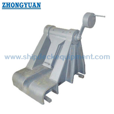
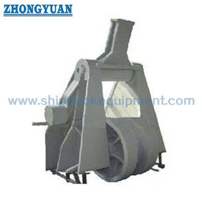
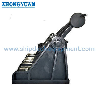
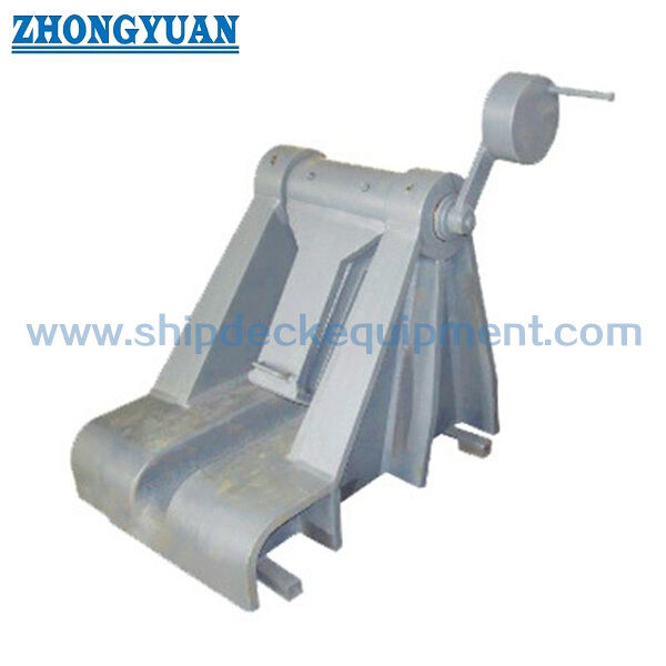
Roller Pawl-Type Anchor Chain Stopper for 70–132 mm Chain | JIS F 2031:1998
Product Details:
| Place of Origin: | China |
| Brand Name: | Zhongyuan Marine Equipmen |
| Certification: | CCS, NK, BV, ABS, DNV, LR, KR, IRS, RS, RINA, CRS, Makers Test Certificate |
| Model Number: | Standard or Customized |
Payment & Shipping Terms:
| Minimum Order Quantity: | 1 Unit |
|---|---|
| Price: | Based on quotation |
| Packaging Details: | Export standard pallet or customized packing |
| Delivery Time: | Based on project requirements |
| Payment Terms: | T/T, L/C |
| Supply Ability: | Customized production based on project requirements |
|
Detail Information |
|||
| Technical Standard: | JIS F2031-1998 | Type: | Roller Pawl Type |
|---|---|---|---|
| Chain Size: | 70-132 Mm | Materials: | Mild Steel, C-Mn Steel, Stainless Steel, Casting Steel, Nodular Cast Iron, Steel Forging, |
| Surface Treatment: | Sandblasting To S2.5 + One Layer Of Epoxy Shop Primer, Customized Surface Treatment Available. | Classification Certificates: | CCS, NK, BV, ABS, DNV, LR, KR, IRS, RS, Etc. |
| Others: | Can Be Customized As Shipyard Request | Weight401 To 2900kg;: | 932 To 4840 Kg |
| Nominal Size:: | 73 - 132 | ||
| Highlight: | JIS F2031 Chain Cable Stopper,Roller Pawl Type Chain Cable Stopper,JIS F2031 Ship Mooring Equipment |
||
Product Description
Roller Pawl-Type Anchor Chain Stopper for 70–132 mm Chain | JIS F 2031:1998
Product Overview
The JIS F 2031:1998 roller pawl-type anchor chain stopper is an anchoring deck fitting used to hold and guide the anchor chain independently of the windlass. The supplied dimensional table corresponds to Annex 4 C Form, which is the roller pawl arrangement with a chain guide. It is intended mainly for JIS F 3303 Grade 2 and Grade 3 anchor chains and is arranged in the anchor-chain line according to the vessel anchoring layout.
For this C Form, the roller assists chain guidance while the pawl provides the mechanical holding function. Selection should be based on the applicable chain diameter, chain grade, JIS F 2031 class requirement, chain lead, windlass and hawse-pipe arrangement, deck foundation, welding detail, operating side, and the approved vessel drawing. The R Form without chain guide uses a different dimensional arrangement and should not be mixed with the C Form data on this page.
Quick Specifications
• Product: roller pawl-type anchor chain stopper, C Form with chain guide → combines anchor-chain guidance with a pawl-type holding arrangement.
• Standard: JIS F 2031:1998, Annex 4 → standard designation: Roller pawl type chain cable stoppers.
• Applicable anchor chain: 70–132 mm → nominal No. 73 to 132 according to the supplied C Form table.
• Chain grade basis: JIS F 3303 Grade 2 / Grade 3 anchor chain → final chain grade and certificate requirement to be confirmed for the vessel.
• Connection basis: Kenter shackle arrangement → compatibility with the actual chain and connecting link should be checked during selection.
• Installation: welded into the ship anchoring arrangement → deck foundation, reinforcement, chain lead and operating clearance require drawing confirmation.
• Standard material basis: component-specific JIS materials → body side frame may be SCW410 cast steel or SS400 welded steel construction according to the standard arrangement.
• Reference calculated mass: 932–4,840 kg for the supplied C Form table → relevant to installation handling, foundation review, packing and freight planning.
Main Technical Parameters
Reference: JIS F 2031:1998 Annex 4, C Form with chain guide. Dimensions are in mm unless otherwise stated.
|
Nominal No. |
Applicable Anchor Chain Dia. (mm) |
B (mm) |
L (mm) |
h (mm) |
h1 (mm) |
D (mm) |
Weld Leg f (mm) |
Calculated Mass (kg) |
|---|---|---|---|---|---|---|---|---|
| 73 | 70 / 73 | 980 | 660 | 125 | 422 | 584 | 15 | 932 |
| 78 | 76 / 78 | 1040 | 700 | 133 | 450 | 624 | 15 | 1120 |
| 84 | 81 / 84 | 1110 | 760 | 143 | 483 | 672 | 17 | 1370 |
| 90 | 87 / 90 | 1190 | 810 | 153 | 515 | 720 | 18 | 1660 |
| 95 | 92 / 95 | 1250 | 860 | 162 | 545 | 760 | 19 | 1940 |
| 102 | 97 / 102 | 1320 | 920 | 175 | 584 | 816 | 20 | 2340 |
| 107 | 105 / 107 | 1390 | 981 | 185 | 617 | 864 | 21 | 2740 |
| 114 | 111 / 114 | 1460 | 1026 | 195 | 651 | 912 | 23 | 3190 |
| 122 | 117 / 122 | 1550 | 1100 | 208 | 695 | 976 | 25 | 3840 |
| 132 | 127 / 132 | 1660 | 1190 | 225 | 750 | 1056 | 26 | 4840 |
Selection & Inquiry Guide
• Step 1: Confirm JIS F 2031:1998 Annex 4 roller pawl type and confirm C Form with chain guide; if R Form without chain guide is required, request the corresponding drawing and dimensional table.
• Step 2: Confirm nominal No., actual anchor-chain diameter, JIS F 3303 chain grade, connecting-link / Kenter-shackle arrangement, and chain certificate requirement.
• Step 3: Confirm the required JIS F 2031 class, operating side, chain lead angle, windlass / cable-lifter position, hawse pipe or fairleader position, and available operating clearance.
• Step 4: Confirm deck foundation, reinforcement, welding arrangement, installation height, and any shipyard restrictions before production.
• Step 5: Confirm material traceability, coating system, inspection scope, NDT or load-test requirement, and classification-society requirement according to the project specification.
• Step 6: Provide quantity, vessel type, installation drawing, delivery destination, required delivery time, and reference photos or GA drawing if available.
Structure
C Form chain guide | Roller assembly | Pawl locking mechanism | Body side frames | Pawl shaft | Roller shaft | Bushes and washers | Welded deck foundation interface
Anchoring, Structure & Engineering Advantages
• The C Form combines a chain guide with the roller-pawl arrangement, helping maintain the intended anchor-chain path while the pawl provides the holding function.
• JIS F 2031 treats the chain stopper as a device independent of the windlass and attached to the ship structure; the foundation and surrounding deck reinforcement therefore form part of the overall load path.
• Roller geometry and chain alignment should avoid excessive local bending of chain links. Chain lead, roller position and the actual chain size should be checked against the vessel arrangement drawing.
• The holding device should remain positively secured in operation and should not loosen progressively toward the open position. Pawl engagement, pin retention and operating clearance are key inspection points.
• For an SS400 welded body-side-frame arrangement, the standard calls for equivalent strength to the cast-steel configuration and specifies additional material requirements around chain-guide and shaft-bearing areas.
• The increasing mass from No. 73 to No. 132 should be considered in workshop handling, shipyard lifting, deck access and foundation planning.
• Inspection, material traceability, NDT, load testing and class witnessing should be defined by the order scope and applicable class or project requirement rather than assumed as standard supply.
Custom Attributes
• Standard: JIS F 2031:1998, Annex 4 → Roller pawl type chain cable stoppers.
• Configuration: C Form with chain guide → supplied table corresponds to Annex 4 Figure 1 body arrangement; R Form without chain guide uses separate dimensions.
• Nominal No.: 73 / 78 / 84 / 90 / 95 / 102 / 107 / 114 / 122 / 132 → select according to chain diameter and vessel drawing.
• Applicable Chain: 70–132 mm, JIS F 3303 Grade 2 / Grade 3 basis → actual chain size and grade to be confirmed before quotation.
• Body Side Frame Material Basis: SCW410 or SS400 according to JIS F 2031 Annex 4 → welded SS400 construction must maintain strength equivalent to the cast-steel arrangement.
• Surface Treatment: Sa 2.5 blast cleaning + epoxy shop primer as a project reference → final coating system follows vessel / shipyard specification and is not a default JIS F 2031 requirement.
• Installation: welded deck foundation → chain lead, deck reinforcement, weld detail and operating clearance require approval by the vessel design / shipyard side.
• Certificate Requirement: available according to project requirement and order scope → material, maker and class documentation to be confirmed before order.
How It Works
Anchor chain is led through the C Form chain-guide and roller arrangement → Roller supports the intended chain path → Pawl is engaged to hold the chain → Chain force is transferred through the stopper body into the ship structure → Pawl is released according to the approved anchoring procedure when chain movement is required
Applications
Forecastle anchoring stations | Anchor windlass arrangements | Large-vessel anchor-chain systems | Grade 2 / Grade 3 anchor-chain routes | Newbuilding projects | Repair and replacement projects
Certifications & Advantages
Certificates and inspection documentation can be arranged according to project requirement, agreed order scope, material traceability and classification-society approval procedure.
Certification: CCS, NK, BV, ABS, DNV, LR, KR, IRS, RS, RINA, CRS, Makers Test Certificate.
Drawing & Photos

FAQ
Q1: What is the main difference between JIS F 2031 Annex 4 C Form and R Form?
A1: C Form is the roller pawl arrangement with a chain guide, while R Form is the arrangement without a chain guide. Their body, roller and pawl dimensions are specified separately and should not be mixed.
Q2: How should the correct nominal No. be selected?
A2: Select the nominal No. according to the actual anchor-chain diameter, chain grade, vessel anchoring arrangement, required JIS class, chain lead, operating side, foundation and approved drawing. The 70–132 mm range on this page is for the supplied C Form table.
Q3: Does the JIS Class A / Class B design basis mean the stopper has a published SWL?
A3: No. JIS F 2031 defines class strength requirements relative to the nominal breaking load of the applicable chain. These class design bases should not be rewritten as a fixed product SWL. The chain grade, design basis, test requirement and class approval scope must be confirmed for the project.