


 |
Electric Engine Room Gantry Crane Ship Deck Equipment
Product Details:
| Place of Origin: | China |
| Brand Name: | Zhongyuan Marine Equipmen |
| Certification: | CCS, NK, BV, ABS, DNV, LR, KR, IRS, RS, RINA, CRS, Makers Test Certificate |
| Model Number: | Standard or Customized |
Payment & Shipping Terms:
| Minimum Order Quantity: | 1 Unit |
|---|---|
| Price: | Based on quotation |
| Packaging Details: | Export standard pallet or customized packing |
| Delivery Time: | Based on project requirements |
| Payment Terms: | T/T, L/C |
| Supply Ability: | Customized production based on project requirements |
|
Detail Information |
|||
| Working Temperature: | -40 To 50℃ Etc. | Surface Treatment: | Sandblasting To S2.5 + 3 Layers Of Epoxy Paint |
|---|---|---|---|
| Classification Certificates: | CCS, NK, BV, ABS, DNV-GL, LR, KR, IRS, RS, RINA | ||
| Highlight: | CCS engine room crane,8m/min engine room crane,Gantry Crane Ship Deck Equipment |
||
Product Description
Electric Engine Room Overhead Travelling Crane | Main Engine Maintenance Crane
Product Overview
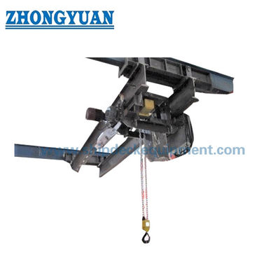
The electric engine room overhead travelling crane is a shipboard overhead travelling lifting appliance installed above or alongside the main engine and major machinery maintenance route. Its purpose is to lift, lower, traverse and transfer cylinder heads, pistons, exhaust valves, turbocharger parts, pumps, motors and other machinery components during overhaul, then position them on a maintenance platform or move them toward an engine-room hatch or removal route.
Unlike a deck crane, this crane works inside the machinery space and must be integrated with the engine-room structure, runway beams, headroom, maintenance clearances and machinery-removal path. The final crane arrangement is therefore selected by SWL, span, hoisting height, bridge travel, trolley travel, hook approach, power supply, control method, vessel inclination criteria and class / flag requirements. Electric remote or pendant control can be supplied according to the approved project arrangement.
Quick Specifications
• SWL range in supplied series: 0.5 / 1 / 2 / 3 / 5 t → covers common machinery-maintenance lifts, with final SWL selected from the heaviest maintenance component plus approved lifting gear.
• Horizontal travelling speed: 6 m/min → reference value from the supplied data for bridge or crane travelling; exact travel arrangement must match the approved GA.
• Hoisting speed: 8 m/min in supplied data → slow / creep speed is not stated and should be confirmed where precise engine-maintenance positioning is required.
• Hoisting height: 5–12 m for 0.5–1 t and 5–40 m for 2–5 t in supplied data → actual hook travel is determined by engine-room deck levels, maintenance platform and removal route.
• Power supply options: AC 380 V 50 Hz 3-phase / AC 415 V 50 Hz 3-phase / AC 440 V 60 Hz 3-phase → one project supply is selected; motor and control components must match the vessel electrical system.
• Control: electric remote or pendant control → operator position, emergency stop and cable / radio arrangement to be confirmed by project.
• Surface preparation: abrasive blast cleaning to Sa 2½ as a typical basis → final primer, intermediate coat, topcoat, DFT and colour follow the vessel coating specification.
• Regulatory basis: engine-room cranes are shipboard lifting appliances → class, flag, load testing, SWL marking and examination requirements must be confirmed for the vessel and delivery date.
Main Technical Parameters
The table below has been rebuilt from the supplied parameter data. Values are reference series data only. Span, bridge travel, trolley travel, hook approach, headroom and self-weight were not provided and must be confirmed from the ship arrangement.
|
SWL |
Horizontal Travel |
Hoisting |
Hoisting |
Power Supply |
Travel / Hoist |
|---|---|---|---|---|---|
| 0.5 | 6 | 8 | 5–12 | 380V 50Hz 3P / 415V 50Hz 3P / 440V 60Hz 3P | 0.2 / 0.8 |
| 1 | 6 | 8 | 5–12 | 380V 50Hz 3P / 415V 50Hz 3P / 440V 60Hz 3P | 0.4 / 1.5 |
| 2 | 6 | 8 | 5–40 | 380V 50Hz 3P / 415V 50Hz 3P / 440V 60Hz 3P | 0.4 / 3.0 |
| 3 | 6 | 8 | 5–40 | 380V 50Hz 3P / 415V 50Hz 3P / 440V 60Hz 3P | 0.8 / 4.5 |
| 5 | 6 | 8 | 5–40 | 380V 50Hz 3P / 415V 50Hz 3P / 440V 60Hz 3P | 0.8 / 7.5 |
Selection & Inquiry Guide
Step 1: Provide the main engine maker / model and maintenance lifting list. Identify the heaviest item to be handled, lifting points, maintenance sequence and any lifting beam, sling or loose gear included in the load.
Step 2: Confirm crane geometry: required SWL, span between runways, bridge travel, trolley travel, hoisting height, hook approach, available headroom, maintenance platform elevation and hatch / machinery-removal route.
Step 3: Confirm vessel design conditions: operating condition, list / heel and trim criteria, machinery-space temperature, humidity, vibration, corrosion category and any low-temperature requirement.
Step 4: Confirm electrical and control data: vessel voltage / frequency / phase, control voltage, pendant or radio remote control, cable festoon / cable chain arrangement, local isolator and ship alarm / interlock interface if required.
Step 5: Confirm class and statutory scope: flag, classification society, SOLAS applicability, plan approval, load test, loose gear, SWL marking, maker documentation and survey witnessing required by the project.
Step 6: Provide quantity, shipyard / vessel project, delivery destination, required delivery time, engine-room GA, structural runway details and any preferred maker list for motors, brakes, controls or electrical components.
Crane Arrangement & Main Components
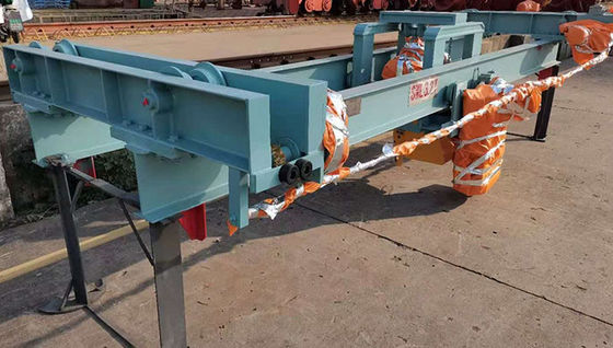
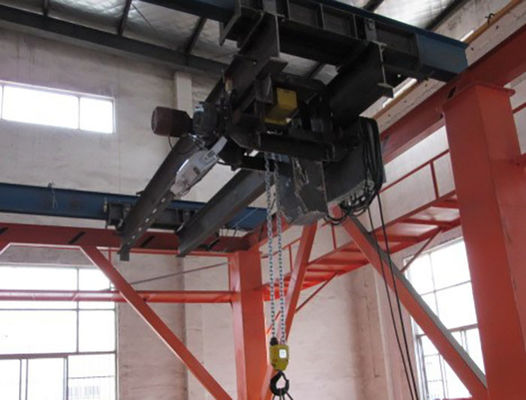
Bridge girder(s) | End carriages and travelling wheels | Shipyard runway / rail interface | Electric trolley or crab | Electric wire-rope hoist | Hook block | Hoisting brake | Travelling drive | Upper / lower hoisting limits | Travel end limits and mechanical stops | Control panel | Pendant / remote control | Power cable system | Buffers | Identification and SWL marking
Engine Room Integration & Maintenance Advantages
• The crane should be laid out around the main engine overhaul path, not selected only by tonnage. Hook coverage must reach the actual cylinder-head, piston, turbocharger or machinery lifting points and the intended landing / removal position.
• Low headroom and hook approach are often decisive in machinery spaces. The selected hoist and trolley arrangement should preserve usable lifting height below deck beams, ventilation trunks, piping and cable trays.
• Runway beams and their supporting ship structure transfer the crane reactions into the hull. Runway section, support spacing, alignment, end stops, weld details and hull reinforcement must be approved as part of the vessel structure arrangement.
• Bridge and trolley travel should allow controlled horizontal transfer without side pulling the hoist rope. The maintenance route should avoid interference with handrails, ladders, exhaust piping, platforms and removable engine components.
• For precise maintenance work, a slow or creep hoisting function may improve positioning. The supplied data only states 8 m/min, so any dual-speed or variable-speed requirement must be confirmed before quotation.
• Maintenance access should be provided for the hoist, brake, rope, drum, sheaves, travel drives, limit switches and electrical equipment so routine inspection can be carried out without major dismantling.
• Noise and vibration can be reduced through appropriate motor, gearbox, wheel and brake selection, but no guaranteed dB value should be published unless it is included in the approved technical specification.
Control, Safety & Electrical Features
• Hoisting brake should be fail-safe so the load is held when power is removed; final brake arrangement and redundancy follow the approved crane design and class requirement.
• Upper and lower hoisting limits and bridge / trolley travel limits are normally included to prevent overtravel. Mechanical end stops or buffers provide an additional physical travel boundary.
• Emergency stop, motor overload / thermal protection and phase / power protection should be included in the electrical design according to the approved schematic.
• An overload protection or load-limiting function may be required by the selected class / statutory rules and crane design; set point, reset logic and test method are to be confirmed.
• Pendant control gives the operator a direct view of the load path. Radio remote control can be considered when required, subject to vessel radio / EMC policy and approved control philosophy.
• The power cable system must accommodate the complete bridge and trolley travel without snagging or interfering with maintenance routes. Festoon, cable chain or other approved arrangements can be used.
• All controls, brakes, limits and direction functions should be checked during commissioning and after major electrical or mechanical repair before the crane is returned to service.
Custom Attributes
• Product Type: Electric engine room gantry / overhead travelling crane → shipboard lifting appliance for machinery maintenance, not a deck cargo crane.
• SWL: 0.5–5 t in supplied series → final capacity selected from the maintenance lifting list and approved design load.
• Crane Arrangement: Single-girder / double-girder / crab arrangement to be confirmed → depends on SWL, span, headroom and machinery-space layout.
• Travel: Bridge travel plus trolley travel → actual coverage and end positions must match the engine-room GA and maintenance route.
• Hoisting Height: 5–40 m within supplied series → project value based on hook path and machinery-removal elevation.
• Power Supply: 380 V 50 Hz 3P / 415 V 50 Hz 3P / 440 V 60 Hz 3P → select one vessel supply and confirm control voltage separately.
• Ambient Temperature: Project-specific → the supplied -40 to +50°C range requires special confirmation of steel, electrical equipment, lubricants and controls; it is not a default ISO 19354 range.
• Coating: Sa 2½ surface preparation plus project paint system → coating type, number of coats, total DFT and colour to be confirmed.
• Control Method: Pendant / wired remote / radio remote option → final arrangement subject to project and class approval.
• Classification: According to vessel requirement → plan approval, survey, load test and certification scope to be confirmed before quotation.
How It Works
Operator positions the bridge above the maintenance area → Trolley moves the hoist to the component lifting point → Hook and approved loose gear are connected → Load is lifted vertically within SWL → Bridge / trolley transfer the load along the planned maintenance route → Load is lowered to the maintenance platform or removal position → Crane is parked and isolated after use
Applications
Main engine cylinder-head handling | Piston and connecting-rod maintenance | Exhaust valve handling | Turbocharger component maintenance | Auxiliary machinery removal | Pump and motor replacement | Engine-room spare-parts transfer | Machinery overhaul and dry-docking maintenance
Class, Testing & Documentation
Engine room cranes are lifting appliances under current shipboard lifting-appliance requirements. For equipment delivered / installed under SOLAS Regulation II-1/3-13, the project should confirm the recognized organization, flag-state interpretation, design approval, installation survey, load test, thorough examination, SWL marking and lifting-appliance register requirements before manufacture.
Certificates and survey involvement can be arranged according to project requirement and selected class procedure; they are not assumed as standard inclusions for every order.
Certification: CCS, NK, BV, ABS, DNV, LR, KR, IRS, RS, RINA, CRS, Makers Test Certificate — available upon request, according to project requirement and subject to class approval / survey scope.
Drawing & Photos
FAQ
Q1: How should the SWL of an engine room crane be selected?
A1: Start from the vessel maintenance lifting list and identify the heaviest component that must be removed or overhauled. Include the mass of lifting beams, slings, shackles or other loose gear as required by the approved lifting arrangement. The selected SWL, span and hook coverage must then be checked against the engine-room GA and class / flag requirements.
Q2: Is this crane the same as a marine deck crane?
A2: No. An engine room crane is an internal shipboard lifting appliance for machinery maintenance. It normally uses overhead bridge / trolley travel inside the machinery space, while a deck crane is generally a deck-mounted crane for external cargo or stores handling. Their arrangement, operating environment and structural interfaces are different.
Q3: What information is needed before quotation and class approval?
A3: Provide SWL, main engine model, maintenance lifting list, span, bridge and trolley travel, hoisting height, headroom, hook approach, runway / support details, vessel power supply, control method, design list / heel and trim, ambient conditions, classification society, flag, coating system, quantity, shipyard and delivery schedule.

Drawing of Electric Engine Room Gantry Crane Ship Deck Equipment