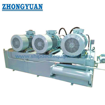
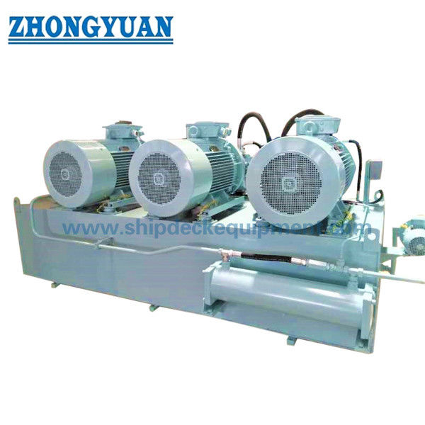
Split Barge Bottom Door Hydraulic Power Unit
Product Details:
| Place of Origin: | China |
| Brand Name: | Zhongyuan |
| Certification: | CCS, NK, BV, ABS, DNV-GL, LR, KR, IRS, RS, RINA, Makers Test Certificate, Etc. |
| Model Number: | Standard and Customized |
Payment & Shipping Terms:
| Minimum Order Quantity: | 1 |
|---|---|
| Price: | As per quotation |
| Packaging Details: | Pallet or Customized |
| Delivery Time: | As per offer |
| Payment Terms: | TT, L/C, Etc. |
| Supply Ability: | Satisfy clients needs |
|
Detail Information |
|||
| Class Certificate: | CCS, NK, BV, ABS, DNV-GL, LR, KR, IRS, RS, RINA, Etc | Working Pressure: | 32MPa,maximum 42MPa |
|---|---|---|---|
| Installed Power: | 22 KW | ||
| Highlight: | 22kw hydraulic power pack system,32MPa hydraulic power pack system,30hp hydraulic pack unit |
||
Product Description
Split Barge Bottom Door Hydraulic Power Unit
Description
The split barge bottom door hydraulic power unit is used to drive open-body cylinder and other special-purpose hydraulic cylinders. This hydraulic system is composed of hydraulic pump, control valve group, differential valve group, hydraulic oil cylinder pressure maintaining valve group, hydraulic oil cylinder overload valve group, hydraulic oil cylinder, etc. In order to ensure that the technical performance and functions of the oil cylinder can achieve the best results, the system is controlled by an open constant power pump, and the key components are imported valves. The system mainly consists of two (one working, one standby) 11kW motor driven hydraulic pump to provide pressure oil, and the corresponding hydraulic control valve drives the cylinder to open and close the body. In addition, the cylinders are equipped with valve blocks for pressure holding, overload, differential and anti-cavitation.
Main Technical Specifications:
Class Certificate: CCS, NK, BV, ABS, DNV-GL, LR, KR, IRS, RS, RINA, Etc.
1. The working pressure of the hydraulic system is about 32MPa, and the maximum pressure is set to 42MPa.
2. The fuel tank has a capacity of 1500 liters.
The total installed power of the system is approximately 22 kW.
3. The main pressure parameters of each cylinder
| Cylinder | design pressure | working pressure | |
| 3.1 | Open body cylinder | 42MPa | 32MPa |
4. Calculation
2. Hydraulic system supply content (one set of ship)
1) Hydraulic power station, including:
1.1 One main fuel tank assembly, 1500L, including:
a) Liquid level gauges, oil temperature gauges, air filters, heaters, etc.;
b) The return oil filter has clogging display and alarm;
c) High temperature alarm, liquid level alarm;
1.2 Motor pump set + pressure control valve set (2x11kW motor + 20YC pump) 2 sets
2) Control valve group, control the following actuator actions:
2.1 Open body cylinder 2
All intermediate pipeline steel pipes and connecting hoses shall be provided by the manufacturer with technical specifications provided by the shipyard.
The list of hydraulic system components is as follows:
| S/N | Quantity | name | model | place of origin |
| 1 | - | Main fuel tank group | ||
| 1.01 | 1 | 1500-liter carbon steel fuel tank | L-1 500 | Shanghai |
| 1.02 | 1 | Fuel tank cap | AB40-19/580A-AL/M | China |
| 1.03 | 1 | Oil level indicator | AB31-23/C1950 | dawn |
| 1.04 | 2 | Shut-off valve | KHNVN-G2-2233 | China |
| 1.05 | 1 | air filter | ELFP5G10W4.X | dawn |
| 1.06 | 1 | Heater | AB32-10/3D380 | China |
| 1.07 | 1 | Level Switch | AB31-04/1200 | In country |
| 1.08 | 1 | Oil temperature switch | AB31-14/3-1A2A3A-Z6 | In country |
| 1.09 | 1 | Shut-off valve | ABZAS-125-016-GP-1X/M | In country |
| 1.10 | 1 | Ball valve | KHNVN-G3/4-2233-12X with limit switch | China |
| 1.11 | 1 | Shut-off valve | ABZAS-125-016-GP-1X/M | China |
| 1.12 | 1 | Junction box | China | |
| 2 | - | Main hydraulic pump unit | ||
| 2.01 | 2 | Motor | 11kW, 380V, 50Hz,. 1 50 0 RPM | South Anhui |
| 2.02 | 2 | Hydraulic pump | 20YC14-1B | Power source |
| 2.03 | 2 | Bell cover | China | |
| 2.04 | 2 | Coupling | China | |
| 2.05 | 8 | Suspension feet | AB33-11/D4-60 | China |
| 2.06 | 2 | Elastic joint | AB22-31/125-16NM | China |
| 2.07 | 4 | Hose Pilot main | L=800mm | Italy |
| 2.08 | 3 | Hose Drain main | L=500mm | Italy |
| 2.09 | 3 | Hose Pressure main | L=800mm | Italy |
| 2.10 | 3 | Hose Suction | L=500mm | Italy |
| 2.11 | 3 | Hose Pressure | L=500mm | Italy |
| 3 | - | Main control valve group | ||
| 3.01 | 1 | Valve block | Z D25-Exxx | Shanghai |
| 3.02 | 1 | Relief valve | DB 30-2-5 X/315X | United States |
| 3.03 | 1 | Reversing valve | 4WE 6 H6X/EG24N9K4 | United States |
| 3.04 | 1 | Check valve | S 52 P2-1X/ | United States |
| 3.05 | 1 | Pressure gauge and hose | 0-400bar, 63mm | Germany |
| 3.06 | 1 | Shut-off valve | DV-08-01.X/0 | Germany |
| 3.07 | 1 | Pressure Sensor | HM17-1X/250-C/V0/0 | United States |
| 3.08 | 1 | Relief valve | DBDS 6 K1X/100 | Germany |
| 3.09 | 1 | Pressure gauge and hose | 0- 400 bar, 63mm | Zeshang |
| 3.10 | 1 | Accumulator | SB330-XXA1/112U-330A | United States |
| 3.11 | 1 | Pressure Switch | HED 1 OA4X/350 | Zeshang |
| 3.12 | 1 | Reversing valve | H-4WEH 25 J6X/6EG24N9ETK4 | Zeshang |
| 3.13 | 1 | Check valve | M-SR 30 KE05-1X/ | China |
| 3.14 | 1 | Pressure gauge and hose | 0-250bar, 63mm | China |
| 3.15 | 1 | Junction box | Shanghai | |
| 4 | - | Return oil filter | ||
| 4.01 | 2 | Check valve | S 52 F2-1X/ | China |
| 4.02 | 2 | Shut-off valve | ABZAS-100-016-G-1X/M | China |
| 4.03 | 1 | Return oil filter | RFLDBN/HC50CAT10D1.X/-L24 | dawn |
| 5 | - | Cylinder valve group | ||
| 5.01 | 1 | Valve block | MD25-Exxx | Shanghai |
| 5.02 | 1 | Solenoid ball valve | 4WEH XX J4X/6EG24N9ETK4 | Germany |
| 5.03 | 1 | Safety valve | RDDA-LAN | United States |
3 the main configuration parameters of the system
Fuel tank capacity: 1500 liters
Total installed power: about 22kW
Supply voltage: 400V x 50Hz
Main pump configuration: 2 constant power controlled axial piston variable pumps
Motor 11kW, 400V, 50Hz, 1450RPM, IP55, Class F.
(2 units work)
Solenoid valve voltage: DC voltage 24V
Four, control cylinder specifications
1) Open body cylinder: 2
Model: FS118 480/200-1850 single rod double acting cylinder
Design pressure: 32 MPa
Test pressure: 42MPa
Installation method: earring connection at both ends, with joint bearing
Piston rod surface treatment: quenching and tempering treatment, double-layer electroplating
Piston rod sheath protection. The rubber sleeve is sand-proof, oil-resistant, alkali-resistant, and acid-resistant, and the effective use period is not less than 4 years
Seal works underwater
1. The interface flanges or pipe joints of the components or assemblies on the hydraulic system are all provided by the shipyard.
2. The steel pipes, hoses, flanges, pipe joints or other pipe fittings on the hydraulic system pipelines are all provided by the shipyard.
3. The cables, special cables or other cable accessories on the electrical system pipelines are all provided by the shipyard.
4. The electrical starting and control system must be provided by an electrical system supplier with past performance experience
5. The piping flushing and pressure test equipment are provided by the shipyard,
![]()
Drawing of Split Barge Bottom Door Hydraulic Power Unit
![]()


