


 |
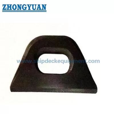
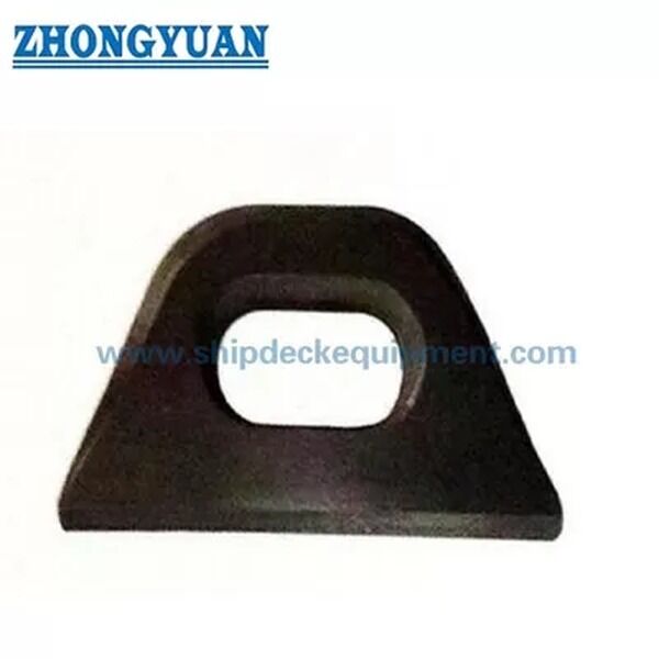
JIS F 3410 Type A & B Mild Steel Forging Steel Oval Eyeplate Ship Mooring Equipment
Product Details:
| Place of Origin: | China |
| Brand Name: | Zhongyuan Marine Equipmen |
| Certification: | CCS, NK, BV, ABS, DNV, LR, KR, IRS, RS, RINA, CRS, Makers Test Certificate |
| Model Number: | Standard or Customized |
Payment & Shipping Terms:
| Minimum Order Quantity: | 1 Unit |
|---|---|
| Price: | Based on quotation |
| Packaging Details: | Export standard pallet or customized packing |
| Delivery Time: | Based on project requirements |
| Payment Terms: | T/T, L/C |
| Supply Ability: | Customized production based on project requirements |
|
Detail Information |
|||
| Standard: | JIS F3410-1999 | Nominal Sizes: | 0.4-50mm |
|---|---|---|---|
| Type: | Type A & B | Permissible Load: | 4 To 500KN |
| Material: | Mild Steel, Stainless Steel C-Mn Steel Forging | Surface Treatment: | Sandblasting To S2.5 + One Layer Of Epoxy Shop Primer |
| Classification Certificates: | CCS, NK, BV, ABS, DNV, LR, KR, BKI, IRS, RS, Etc | ||
| Highlight: | JIS F3410 500KN marine eye plate,500KN marine eye plate,ship steel eye plate 500KN |
||
Product Description
Ship Oval Eyeplate JIS F 3410 Type A & B | Forged or Steel Plate Cut Marine Attachment
Product Overview
The JIS F 3410 Type A and Type B ship oval eyeplate is a welded marine attachment fitting used for fixing rope terminals, shackles, pulleys, and related connection components on vessel structures. It is selected by standard type, nominal size, permissible load, installation position, material route, weld detail, and the strength of the parent ship structure.
Type A is normally used as a general-purpose eyeplate, such as deck-mounted attachment positions. Type B is intended for lifting boom guy eyeplate arrangements and should be confirmed by project drawing. This page treats the product as a marine attachment fitting, not as a standalone lifting product; cargo-handling, lifting, or class-approved use must be checked by load case, welding detail, parent structure, and classification approval.
Quick Specifications
- Product type: Ship oval eyeplate → welded attachment point for rope terminals, shackles, pulleys, and marine connection components.
- Standard and type: JIS F 3410-1999 Type A & Type B → reference for type designation, dimensions, material basis, and ordering description.
- Nominal size range: 0.4 to 50 → standard designation based on permissible load, not a direct millimeter size.
- Permissible load range: 4 to 500 kN → selection reference for tensile loading; final use must match vessel structure and project approval.
- Material route: forged alloy steel / C-Mn steel or steel plate cut to shape → exact grade, heat treatment, and weldability should be confirmed before quotation.
- Manufacturing focus: smooth section transition, oval eye geometry, crack / flaking control, machining or forging accuracy, and weld-zone preparation.
- Type A mounting weld reference: s min. 6 to 35 mm and g min. 4 to 22 mm → useful for preliminary layout, but final welding detail follows the shipyard drawing.
- Surface treatment: Sa 2.5 blasting + one layer epoxy shop primer as reference → final coating, galvanizing, or stainless steel finishing should follow project requirements.
Main Technical Parameters
| Nominal size |
Permissible load kN |
a | b | C | d | e | f | h | I | r1 | r2 | Mounting of type A Welding s min. |
Mounting of type A Welding g min. |
| 0.4 | 4 | 22 | 15 | 42 | 10 | 15 | 8 | 32,5 | 65 | 17,5 | 3 | 6 | 4 |
| 0.6 | 6,3 | 28 | 19 | 52 | 12 | 19 | 8 | 40,5 | 0 | 21,5 | 4 | 6 | 4 |
| 1 | 10 | 35 | 22 | 67 | 16 | 25 | 8 | 52 | 95 | 27 | 5 | 6 | 4 |
| 1.6 | 16 | 42 | 24 | 82 | 20 | 33 | 8 | 65 | 120 | 32 | 5 | 7 | 4 |
| 2 | 20 | 50 | 27 | 100 | 25 | 35 | 12 | 73,5 | 132 | 38,5 | 5 | 9 | 6 |
| 2,5 | 25 | 55 | 29 | 105 | 25 | 39 | 12 | 78,5 | 140 | 39,5 | 6 | 9 | 6 |
| 3 | 31,5 | 66 | 33 | 126 | 30 | 42 | 12 | 88,5 | 180 | 46,5 | 7 | 10 | 6 |
| 4 | 40 | 77 | 36 | 147 | 35 | 48 | 15 | 101 | 210 | 53 | 7 | 12 | 7 |
| 5 | 50 | 87 | 41 | 167 | 40 | 57 | 18 | 117,5 | 225 | 60,5 | 8 | 14 | 9 |
| 6 | 63 | 91 | 45 | 171 | 40 | 66 | 18 | 128,5 | 240 | 62,5 | 8 | 14 | 9 |
| 8 | 80 | 101 | 51 | 201 | 50 | 73 | 20 | 148,5 | 270 | 75,5 | 10 | 17 | 10 |
| 10 | 100 | 117 | 56 | 217 | 50 | 80 | 22 | 158 | 300 | 78 | 10 | 17 | 11 |
| 12 | 125 | 128 | 61 | 248 | 60 | 87 | 24 | 177,5 | 335 | 90,5 | 12 | 20 | 12 |
| 16 | 160 | 145 | 67 | 265 | 60 | 95 | 26 | 188,5 | 370 | 93,5 | 12 | 20 | 13 |
| 20 | 200 | 157 | 73 | 297 | 70 | 105 | 28 | 211,5 | 420 | 106,5 | 14 | 25 | 14 |
| 25 | 250 | 170 | 80 | 331 | 80 | 120 | 32 | 240 | 470 | 120 | 16 | 30 | 16 |
| 32 | 315 | 194 | 88 | 374 | 90 | 130 | 36 | 264 | 530 | 134 | 18 | 30 | 18 |
| 40 | 400 | 220 | 98 | 420 | 100 | 145 | 40 | 294 | 570 | 149 | 20 | 35 | 20 |
| 50 | 500 | 240 | 108 | 460 | 110 | 155 | 45 | 319 | 630 | 164 | 22 | 35 | 22 |
Selection & Inquiry Guide
Step 1: Confirm JIS F 3410 Type A or Type B according to the vessel drawing, attachment purpose, and installation position.
Step 2: Confirm nominal size and permissible load from 0.4 to 50 / 4 to 500 kN, and state whether the load case is deck attachment, rope terminal fixing, shackle connection, pulley connection, or lifting boom guy arrangement.
Step 3: Confirm parent structure, weld detail, reinforcement, load direction, and whether class approval, witness inspection, or additional calculation is required.
Step 4: Confirm material and manufacturing route: forged alloy steel, forged C-Mn steel, steel plate cut + machined / forged finish, stainless steel, or special steel requirement.
Step 5: Confirm surface treatment, marking method, NDT / inspection requirement, certificate scope, quantity, delivery destination, and required delivery time.
Step 6: Provide GA drawing, installation drawing, existing product photo, or replacement sample if available, especially when ordering Type B or project-specific dimensions.
Structure
Oval eye opening | Forged or steel plate cut body | Smooth radiused transitions | Type A welded mounting area | Type B guy-eyeplate configuration | Low-stress marking area | Blasted and shop-primed or specified surface finish
Forging, Steel Plate Cutting & Welding Advantages
- Forged construction is suitable when the project requires a compact load-bearing eye shape with controlled section transition and confirmed mechanical properties.
- Steel plate cutting can be used when the material grade, thickness, edge preparation, machining, and final section shape satisfy the project drawing and inspection requirement.
- Smooth transition around the oval eye reduces abrupt local contact and helps achieve better seating of shackles, rope terminals, or pulley fittings.
- The finished surface should be free from visible cracks and flaking; this is especially important around the eye opening, radiused transition, and welded mounting zone.
- For forged eyeplates, normalizing after completion may be required according to the manufacturing route and standard / project requirement.
- Type A weld reference dimensions s and g are useful for preliminary installation checking, but the shipyard or design office must confirm weld detail and local reinforcement.
- Permissible load should not be mixed with SWL, MBL, test load, or rope breaking load. The final approved load depends on the eyeplate, weld, parent structure, and inspection scope together.
- Material certificate, maker certificate, class certificate, NDT record, or witness inspection can be arranged according to the confirmed order scope.
Custom Attributes
- Standard: JIS F 3410-1999 → use when the project specification calls for ship oval eyeplate dimensions and ordering designation.
- Type: Type A / Type B → Type A for general use such as deck mounting; Type B for lifting boom guy eyeplate arrangement subject to drawing confirmation.
- Nominal Size: 0.4 / 0.6 / 1 / 1.6 / 2 / 2.5 / 3 / 4 / 5 / 6 / 8 / 10 / 12 / 16 / 20 / 25 / 32 / 40 / 50 → select according to permissible load and installation drawing.
- Permissible Load: 4 to 500 kN → standard reference load for selection; do not replace project-specific approval or parent-structure verification.
- Material: Alloy steel forging, C-Mn steel forging, or steel plate cut construction → final grade, weldability, heat treatment, and certificate scope to be confirmed.
- Surface Treatment: Sa 2.5 blasting + epoxy shop primer → final paint system, galvanizing, or stainless steel finish according to vessel specification.
- Inspection: Visual surface check as basic requirement → NDT, proof testing, or class witness inspection available according to project requirement.
- Certificate Requirement: Available upon request according to order scope → class approval is subject to project document review and inspection arrangement.
How It Works
Rope terminal / shackle / pulley fitting connects to the oval eye → Tensile force is carried through the smooth eye section → Load is transferred into the welded mounting area → Parent deck, boom, or supporting structure distributes the load → Inspection, marking, and final coating are completed according to project requirement
Applications
Ship deck attachment points | Rope terminal fixing | Shackle connection | Pulley or block connection | Deck mooring accessory arrangement | Lifting boom guy eyeplate arrangement | Newbuilding and replacement projects
Certifications & Advantages
Certificates can be arranged according to project requirement, inspection scope, material traceability, and class society approval procedure.
Certification: CCS, NK, BV, ABS, DNV, LR, KR, IRS, RS, RINA, CRS, Makers Test Certificate.
Drawing & Photos

FAQ
Q1: What is the difference between JIS F 3410 Type A and Type B?
A1: Type A is the general-use configuration, commonly used for deck-mounted attachment positions. Type B is intended for lifting boom guy eyeplate arrangements and should be checked by project drawing. For Type B orders, additional details such as plate length or installation dimensions may be required.
Q2: Is the permissible load the same as SWL or a lifting capacity?
A2: No. The table provides permissible load for the standard eyeplate selection basis. It should not be renamed as SWL, MBL, rope breaking load, or proof load. Any lifting, cargo-handling, or class-approved use must be confirmed by load direction, weld detail, parent structure, inspection scope, and class approval.
Q3: Should the eyeplate be forged or made by steel plate cutting?
A3: Both routes can be discussed. Forging is suitable when controlled section transition and mechanical properties are required. Steel plate cutting can be used when the specified steel grade, thickness, edge preparation, machining, and final profile meet the drawing and inspection requirement. The route should be confirmed before quotation.