


|
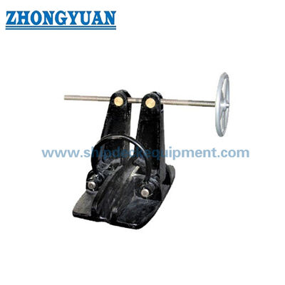
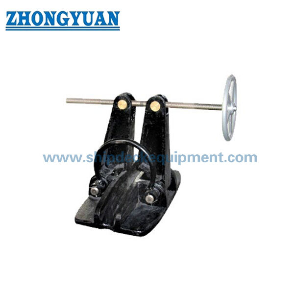
Casting Screw Bar Type Anchor Chain Stopper CB/T 178 Type A Ship Mooring Equipment
Product Details:
| Place of Origin: | China |
| Brand Name: | Zhongyuan Marine Equipmen |
| Certification: | CCS, NK, BV, ABS, DNV, LR, KR, IRS, RS, RINA, CRS, Makers Test Certificate |
| Model Number: | Standard or Customized |
Payment & Shipping Terms:
| Minimum Order Quantity: | 1 Unit |
|---|---|
| Price: | Based on quotation |
| Packaging Details: | Export standard pallet or customized packing |
| Delivery Time: | Based on project requirements |
| Payment Terms: | T/T, L/C |
| Supply Ability: | Customized production based on project requirements |
|
Detail Information |
|||
| Technical Standard: | CB/T 178-96 | Type: | Screw Type A |
|---|---|---|---|
| Chain Size: | 22-66mm | Materials: | Mild Steel, C-Mn Steel, Stainless Steel, Casting Steel, Nodular Cast Iron, Steel Forging |
| Surface Treatment: | Sandblasting To S2.5 + One Layer Of Epoxy Shop Primer, Polished Stainless Steel, Customized Surface Treatment Available. | Classification Certificates: | CCS, NK, BV, ABS, DNV, LR, KR, RINA, IRS, RS, Etc |
| Highlight: | 66mm mooring chain stopper,66mm ship mooring equipment,cb/t 178 type a ship mooring equipment |
||
Product Description
Screw Type Anchor Chain Stopper | CB/T 178 Type A for Workboats and Small Vessels
Product Overview
The CB/T 178-1996 Type A screw type anchor chain stopper is a deck-mounted anchoring component for U2 / Grade 2 anchor chain from 22 mm to 66 mm. Its screw-operated clamping structure secures the anchor chain and transfers the retained chain force into the stopper foundation and supporting deck structure, reducing sustained anchor-chain load on the windlass brake and cable lifter. The product is particularly relevant to small and medium workboats, tugboats, barges, service vessels, and engineering vessels where the selected U2 chain size and deck arrangement match the Type A range.
For a complete anchoring deck solution, the stopper can be coordinated with a chain guide roller or bow/deck roller, the anchor windlass cable-lifter centerline, hawse pipe or anchor pocket, chain pipe, and deck foundation. The matched roller guides the chain lead and elevation; it must not be assumed to increase the stopper load capacity unless the complete arrangement has been specifically designed and approved. Final chain grade, foundation, deck reinforcement, load direction, coating, inspection, and class scope should be confirmed from the vessel anchoring arrangement.
Quick Specifications
- Standard and type: CB/T 178-1996 Type A screw / spiral chain stopper → reference configuration for U2 anchor-chain securing.
- Applicable anchor chain: 22-66 mm U2 / Grade 2 chain only → Type B or another approved design is required for U3 chain or larger sizes.
- Reference load basis: 80% of the matched U2 anchor-chain breaking load → this is not a declared product SWL and should not be relabeled as SWL.
- Operating method: manually adjusted screw mechanism → positive mechanical opening and closing without hydraulic or electric power.
- Installation: welded directly to the deck or mounted on a project-specific base → weld detail, load direction, and local deck reinforcement require drawing confirmation.
- Matched equipment: chain guide roller / bow roller available as a coordinated selection → chain size, roller groove, centerline, and elevation must match the windlass-to-hawse lead.
- Material and protection: cast-steel and carbon-steel parts with protected moving surfaces → final material grade, coating system, lubrication points, and certificate scope are confirmed per order.
Main Technical Parameters
| Anchor Chain Size |
B | B1 | B2 | B3 | B4 | B5 | b | b1 | c | d | d1 | d2 | |
| 22~26 | 280 | 104 | 40 | 94 | 76 | 84 | 20 | 35 | 190 | T26 x 8/2 | 250 | 25 | |
| 28~32 | 310 | 118 | 45 | 114 | 92 | 90 | 25 | 40 | 210 | T28 X 8/2 | 320 | 26 | |
| 34-38 | 360 | 131 | 50 | 136 | 110 | 105 | 30 | 45 | 250 | T30 x 10/2 | 320 | 30 | |
| 10~44 | 420 | 152 | 55 | 160 | 128 | 120 | 35 | 50 | 290 | T32 x 10/2 | 400 | 34 | |
| 46~48 | 480 | 172 | 65 | 186 | 145 | 130 | 40 | 60 | 330 | T36 X 10/2 | 400 | 36 | |
| 52~58 | 550 | 192 | 75 | 211 | 166 | 150 | 45 | 75 | 380 | T40 x 10/2 | 400 | 40 | |
| 60-66 | 610 | 212 | 85 | 250 | 190 | 170 | 50 | 90 | 110 | T44 x 12/2 | 500 | 40 | |
| Anchor Chain Size |
H | H1 | H2 | H3 | h | L | L1 | L2 | R | R1 | r | r1 | Weight kg |
| 22~26 | 335 | 105 | 70 | 1 75 | 42 | 500 | 275 | 265 | 45 | 95 | 22 | 40 | 90 |
| 28~ 32 | 400 | 125 | 80 | 204 | so | 550 | 330 | 320 | 50 | 105 | 28 | 50 | 122 |
| 34~38 | 455 | 135 | 90 | 235 | 60 | 600 | 375 | 365 | 55 | 125 | 33 | 55 | 163 |
| 40~ 44 | 515 | 150 | 100 | 271 | 70 | 670 | 430 | 415 | 65 | 145 | 37 | 65 | 238 |
| 46~48 | 585 | 175 | 115 | 307 | 80 | 770 | 480 | 165 | 75 | 165 | 42 | 75 | 353 |
| 52~58 | 680 | 200 | 130 | 360 | 90 | 970 | 565 | 545 | 85 | 190 | 46 | 85 | 518 |
| 60~66 | 775 | 225 | 150 | 410 | 105 | 1000 | 640 | 615 | 100 | 220 | 55 | 100 | 772 |
Selection & Inquiry Guide
Step 1: Confirm CB/T 178-1996 Type A, U2 / Grade 2 anchor-chain diameter, chain certificate basis, and whether the vessel is a newbuilding, conversion, or replacement project.
Step 2: Provide the anchoring arrangement showing anchor windlass cable lifter, chain stopper, chain guide roller or bow roller, hawse pipe / anchor pocket, chain pipe, and chain-locker direction.
Step 3: Match the stopper and guide roller to the same chain size, then confirm chain centerline, roller axis, contact geometry, elevation, allowable lead angle, and clear operating space.
Step 4: Confirm direct deck welding or base-mounted installation, foundation footprint, load direction, weld detail, local deck reinforcement, and access for screw operation and maintenance.
Step 5: Confirm component material grades, Sa 2.5 blasting and primer or other coating system, corrosion-protection details, lubrication requirement, and any stainless or galvanized option subject to technical approval.
Step 6: State quantity, vessel type, classification society requirement, certificate and witness scope, delivery destination, required delivery time, and project drawing or reference photo.
Structure
Cast-steel base / body | Screw-operated clamping bar and operating parts | Anchor-chain seating and contact area | Deck-welded or base-mounted foundation | Lubricated moving parts | Project-matched chain guide roller interface | Protective coating system
Anchoring System, Casting & Engineering Advantages
- The screw mechanism provides controlled mechanical engagement with the selected chain link and allows the stopper to be opened or secured manually without a powered actuator.
- A correctly matched chain guide roller keeps the chain lead aligned between the cable lifter, stopper, and hawse arrangement, helping reduce side loading, link twisting, and local impact caused by poor geometry.
- The stopper transfers retained chain force into its foundation and supporting hull structure; deck reinforcement and welding details therefore form part of the anchoring-system design, not only the product supply.
- Cast-steel surfaces and chain-contact areas should be clean and free from burrs, cracks, or defects affecting strength. Machined or moving parts require dimensional control, lubrication, and corrosion protection.
- The seven Type A size groups allow selection across 22-66 mm U2 chain while retaining a consistent screw-operated arrangement for small and medium vessel anchor decks.
- A coordinated package review can identify interface mismatches before production, including chain size, roller groove, windlass centerline, hawse lead, base height, installation access, and coating sequence.
- Project-specific customization should be limited to approved interfaces, foundation height, coating, and accessory scope; changes affecting the standard load path or chain engagement require drawing and class review.
Custom Attributes
- Standard: CB/T 178-1996 reference configuration → confirm project acceptance and required edition with the shipyard, owner, and classification society.
- Product Category: Anchoring equipment / anchor chain stopper → not a mooring-line fitting and not a lifting product.
- Type: Type A screw / spiral type → manually operated chain-securing arrangement for U2 anchor chain.
- Chain Size: 22-66 mm across seven standard size groups → state the exact chain diameter in the inquiry.
- Chain Grade: U2 / Grade 2 → U3 chain is outside the declared Type A application.
- Load Basis: 80% of matched U2 anchor-chain breaking load as reference → do not convert this value into product SWL without an approved calculation and test basis.
- Installation: Direct deck welding or installation on a base → foundation, weld, deck reinforcement, and load direction to be confirmed by arrangement drawing.
- Materials: Cast steel, ordinary carbon steel, and quality carbon steel are used for different parts in public technical references → exact grades and substitutions to be confirmed.
- Surface Treatment: Sa 2.5 blasting + epoxy shop primer available for suitable non-machined surfaces → threads, pins, bearings, and moving interfaces require protected / lubricated treatment.
- Matched Supply: Chain guide roller, anchor chain, accessories, and anchoring-deck interface support available according to quotation scope → not included by default.
- Certificates: Material, maker, inspection, or class documentation according to project requirement → subject to agreed inspection scope and class approval.
How It Works
Anchor chain leaves the windlass → Matched guide roller controls chain lead and elevation → Screw mechanism secures the designated chain position → Retained force passes through the stopper foundation into the reinforced deck → Windlass is relieved from sustained chain pull → Moving parts are released, inspected, and lubricated
Applications
Small and medium workboats | Tugboats | Barges | Dredging support vessels | Service and utility vessels | Inland and coastal vessels | Engineering vessels | Newbuilding and anchor-deck retrofit packages
Certifications & Advantages
Certificates and inspection can be arranged according to project requirement, order scope, material traceability, test requirement, and classification society approval procedure.
Certification: CCS, NK, BV, ABS, DNV, LR, KR, IRS, RS, RINA, CRS, Makers Test Certificate.
Drawing & Photos

FAQ
Q1: Is the stated 80% of U2 anchor-chain breaking load the SWL of the chain stopper?
A1: No. It is a reference load basis related to the breaking load of the matched U2 anchor chain. It should not be published as product SWL. The final design load, foundation calculation, test load, and acceptance criteria should follow the vessel specification and class requirement.
Q2: Why should the Type A chain stopper be selected together with a chain guide roller?
A2: The stopper secures and retains the chain, while the guide roller controls the chain path, elevation, and local contact as the chain moves between the windlass and hawse arrangement. Coordinated selection helps avoid side loading, poor chain seating, roller mismatch, and installation-height conflicts.
Q3: What can be included in a complete anchoring deck solution?
A3: The quotation can cover the Type A stopper, matched chain guide roller or bow roller, anchor chain and accessories, interface review with the windlass and hawse / chain-pipe arrangement, coating, documentation, and foundation-input drawings. The exact supply boundary and class scope must be confirmed before quotation.