


 |
Super Arch Rubber Fender for Ports and Marine Terminals
Product Details:
| Place of Origin: | China |
| Brand Name: | Zhongyuan Marine Equipmen |
| Certification: | CCS, NK, BV, ABS, DNV, LR, KR, IRS, RS, RINA, CRS, Makers Test Certificate |
| Model Number: | Standard or Customized |
Payment & Shipping Terms:
| Minimum Order Quantity: | 1 Unit |
|---|---|
| Price: | Based on quotation |
| Packaging Details: | Export standard pallet or customized packing |
| Delivery Time: | Based on project requirements |
| Payment Terms: | T/T, L/C |
| Supply Ability: | Customized production based on project requirements |
|
Detail Information |
|||
| Type: | SA | Applicable To: | Quayside, Dockside |
|---|---|---|---|
| Certification: | CCS, BV, ABS And SGS | ||
| Highlight: | SA Marine Rubber Fender,quayside Marine Rubber Fender,dockside super arch rubber fender |
||
Product Description
Super Arch Rubber Fender for Ports and Marine Terminals
Product Overview
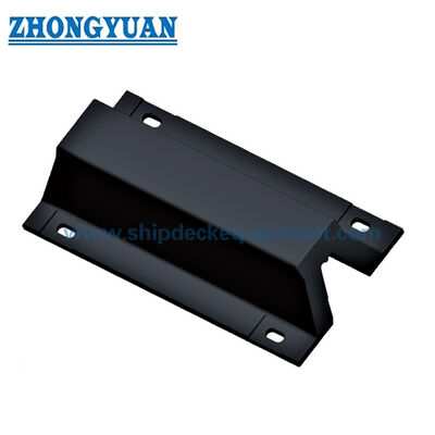
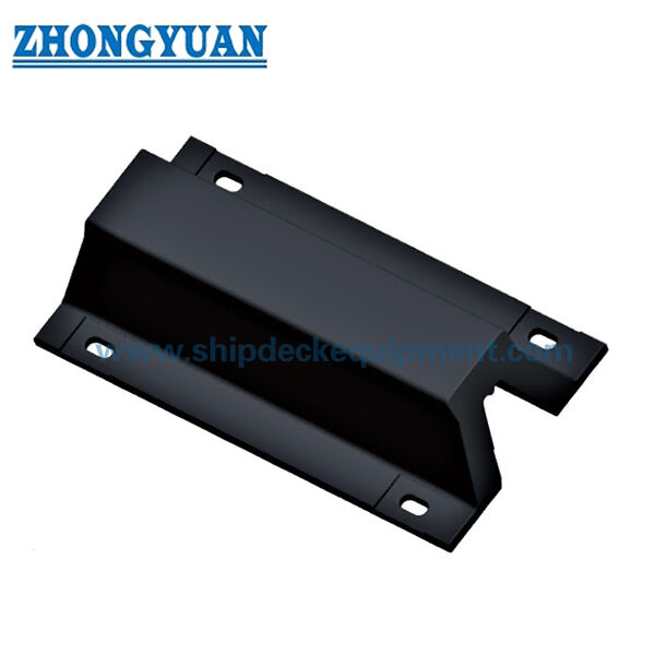
Super Arch Rubber Fender for Ports and Marine Terminals is a one-piece fixed marine rubber fender designed for direct mounting to quay, dock and berth structures. Its arch-shaped body compresses under berthing load to absorb vessel energy while transmitting the corresponding reaction force into the supporting structure.
The supplied series covers nominal fender heights from 250 to 800 mm and selected unit lengths from 1,000 to 2,000 mm. Two published performance groups are available: HR (High Reaction) and SR (Standard Reaction). The catalogue provides reaction force and energy absorption at 52.5% and 55% compression, allowing the fender size, length and performance group to be matched to the berth energy and allowable reaction requirements.
Quick Specifications
- Product type: One-piece arch-shaped fixed marine rubber fender
- Supplied nominal height range: 250–800 mm
- Supplied unit lengths: 1,000–2,000 mm depending on fender height
- Published performance groups: HR High Reaction | SR Standard Reaction
- Primary published compression point: 52.5% | additional performance reference: 55%
- Catalogue performance tolerance: ±10%
- Installation form: Direct bolted mounting to the berth structure with project-specific anchor and reinforcement design.
Rubber material is controlled to the confirmed solid-fender physical-property specification, including tensile strength ≥16 MPa, elongation at break ≥400%, hardness ≤78 Shore A and compression set ≤30%, with applicable ISO test methods.
Structure & Fender System Configuration
One-piece moulded and vulcanized rubber arch body | broad mounting feet | direct rubber contact face | elongated fixing openings / bolt positions according to the supplied geometry | anchor and head-bolt interface to the berth structure.
The arch geometry provides a compact direct-mount arrangement without requiring a front panel for the standard rubber-faced configuration. The final anchor size, material, embedment, edge distance and supporting reinforcement are determined from the selected fender performance and the project-specific berth structure.
Main Technical Specifications:
| TYPES SAHX L | H | L | Ll | B | Bl | B2 | c | d | e | f | h | P | s | n |
| SA250X1000 | 250 | 1000 | 1000 | 164 | 500 | 410 | 70 | 32 | 90 | )25 | 27.5 | 620 | 160 | 2 |
| SA300X1000 | 300 | 1000 | 1150 | 225 | 600 | 490 | 140 | 35 | 105 | 140 | 33 | 870 | 195 | 1 |
| SA300XI500 | 300 | 1500 | 1650 | 225 | 600 | 490 | 140 | 35 | 105 | 140 | 33 | 685 | J95 | 2 |
| SA300X2000 | 300 | 2000 | 2150 | 225 | 600 | 490 | 137.5 | 35 | 105 | 140 | 33 | 625 | 195 | 3 |
| SA400X1000 | 400 | 1000 | 1200 | 300 | 800 | 670 | 150 | 41 | 120 | 165 | 40 | 900 | 260 | 1 |
| SA400X1500 | 400 | 1500 | 1700 | 300 | 800 | 670 | 150 | 41 | 120 | 165 | 40 | 700 | 260 | 2 |
| SA400 X 2000 | 400 | 2000 | 2200 | 300 | 800 | 670 | 147.5 | 41 | 120 | 165 | 40 | 635 | 260 | 3 |
| SA500X 1000 | 500 | 1000 | 1250 | 375 | 1000 | 840 | 160 | 47 | 140 | 180 | 45 | 930 | 325 | 1 |
| SA500X1500 | 500 | 1500 | 1750 | 375 | 1000 | 840 | 160 | 47 | 140 | 180 | 45 | 715 | 325 | 2 |
| SA500X2000 | 500 | 2000 | 2250 | 375 | 1000 | 840 | 157.5 | 47 | 140 | 180 | 45 | 645 | 325 | 3 |
| SA600X1000 | 600 | 1000 | 1300 | 450 | 1200 | 1010 | 170 | 50 | 160 | 195 | 54 | 960 | 390 | 1 |
| SA600X1500 | 600 | 1500 | 1800 | 450 | 1200 | 1010 | 170 | 50 | 160 | 195 | 54 | 730 | 390 | 2 |
| SA600 X 2000 | 600 | 2000 | 2300 | 450 | 1200 | 1010 | 167.5 | 50 | 160 | 195 | 54 | 655 | 390 | 3 |
| SA800X1000 | 800 | 1000 | 1400 | 600 | 1600 | 1340 | 180 | 68 | 260 | 270 | 72 | 1040 | 520 | 1 |
| SA800X1500 | 800 | 1500 | 1900 | 600 | 1600 | 1340 | 180 | 68 | 260 | 270 | 72 | 770 | 520 | 2 |
|
TYPES AHXL |
HR High Reaction Force | SR Standard Reaction Force | Tolerance % |
||||||
| 52.50% | 55% | 52.50% | 55% | ||||||
|
Reaction Force |
Energy Absorption |
Reaction Force |
Energy Absorption |
Reaction Force (KN) |
Energy Absorption (KJ) |
Reaction Force (KN) |
Energy Absorption (KJ) |
||
| SA250X 1000 | 203.3 | 18.2 | 282.8 | 19.1 | 168.1 | 15.7 | 233.3 | 17.1 | ±10 |
| SA300X 1000 | 244 | 30.4 | 339.1 | 32.3 | 201.9 | 25.5 | 280.3 | 27.4 | |
| SA300X 1500 | 366.5 | 45.6 | 508.6 | 49 | 320.8 | 38.2 | 420.4 | 41.2 | |
| SA300X2000 | 488 | 60.8 | 678.2 | 64.7 | 403.8 | 51 | 560.6 | 54.9 | |
| SA400X 1000 | 325.4 | 54.9 | 451.8 | 58.8 | 269.5 | 45.1 | 374.3 | 48 | |
| SA400X 1500 | 488 | 82.3 | 678 | 88.2 | 404 | 67.6 | 561.5 | 72 | |
| SA400X2000 | 650.8 | 109.8 | 903.6 | 117.6 | 539 | 90.2 | 748.6 | 96 | |
| SA500X 1000 | 406.7 | 85.3 | 564.5 | 91.1 | 337.1 | 70.6 | 468.4 | 75.5 | |
| SA500X 1500 | 610 | 128 | 846.7 | 137 | 505.7 | 105.9 | 702.5 | 113.3 | |
| SA500X2000 | 813.4 | 170.5 | 1129 | 182.3 | 647.3 | 141.1 | 936.8 | )51.0 | |
| SA600X 1000 | 488 | 123.5 | 678.2 | 132.2 | 403.8 | 101.9 | 560.6 | 108.8 | |
| SA600X 1500 | 732 | 185.2 | 1017.3 | 198.5 | 605.6 | 152.9 | 840.8 | 163.2 | |
| SA600X2000 | 976.1 | 247 | 1356.3 | 264.6 | 807.5 | 203.8 | 1121.1 | 217.6 | |
| SA800X 1000 | 650.7 | 218.5 | 903.6 | 234.2 | 539 | 181.3 | 748.7 | 194 | |
| SA800X 1500 | 976.1 | 328.3 | 1355.4 | 351.3 | 808.5 | 272 | 1123.1 | 291 | |
Selection & Inquiry Guide
Step 1 – Define the berth and vessel requirement: Provide vessel type and size range, berth arrangement, design berthing energy and allowable reaction force.
Step 2 – Select fender height, length and performance group: Match the required energy/reaction envelope using the published 52.5% data and the available HR or SR group.
Step 3 – Confirm the structural interface: Provide the quay/dock drawing, concrete or steel support condition, available installation space and required anchor arrangement.
Step 4 – Confirm operating and verification conditions: State design temperature, berthing angle/velocity assumptions, required ITP, full-scale performance verification and documentation scope.
Step 5 – Confirm quantity, delivery destination, required delivery date and any replacement/interchange requirements.
Key Engineering Advantages
- The one-piece arch geometry provides a compact direct-mount fender arrangement with relatively few system components.
- Multiple supplied lengths for the same nominal height allow the energy/reaction capacity to be matched to berth requirements without creating separate thin product pages for every length.
- HR and SR performance groups provide two practical reaction/energy choices within the same dimensional family.
- The arch profile is suited to fixed berths where shear components and oblique vessel contact must be considered together with the normal compression load.
Installation & System Interface
The Super Arch fender is bolted directly to the berth support structure through the mounting feet. Installation clearance must allow the rubber body to compress and recover without interference from adjacent steelwork, concrete projections or neighbouring fenders.
For reinforced-concrete structures, cast-in or suitable post-installed anchors may be used subject to structural verification. Final anchor size, material, corrosion protection, embedment depth, edge distance, bolt spacing and local reinforcement are determined from the selected fender performance, the support condition and the approved project GA / anchor layout. A single universal anchor size should not be applied to every fender grade or berth.
Inspection & Documentation
Baseline quality control includes visual inspection, dimensional verification and rubber physical-property testing. Full-scale compression/performance verification can be included in the project ITP to confirm the agreed reaction-force and energy-absorption requirements under defined test conditions.
PIANC Fender Guidelines 2024 (MarCom WG211) are used as the current engineering reference for fender-system design, manufacturing and testing principles. Any project claim of compliance, type approval, third-party witnessing or class certification is stated only when the corresponding scope has been agreed and documented.
Applications
RoRo berths | general cargo berths | workboat harbors | barge and tug berths | quay-side and dock-side general berthing.
Drawing & Photos

FAQ
Q1: How should HR and SR Super Arch fenders be selected? — Select the group that satisfies the required energy absorption while keeping reaction force within the berth and vessel limits; then verify operating corrections and structural loads for the project.
Q2: Why is the same fender height supplied in different lengths? — Length changes the total rubber volume and therefore the published reaction/energy capacity. Select the length from the required performance and the available berth layout rather than by height alone.
Q3: What inspection documents can be specified? — The order ITP can define material test records, dimensional inspection, full-scale performance verification, maker documentation and third-party witnessing where required.