


 |
ISO 17357-1 Floating Pneumatic Rubber Fender for Ship-to-Ship and Berthing
Product Details:
| Place of Origin: | China |
| Brand Name: | Zhongyuan Marine Equipmen |
| Certification: | CCS, NK, BV, ABS, DNV, LR, KR, IRS, RS, RINA, CRS, Makers Test Certificate |
| Model Number: | Standard or Customized |
Payment & Shipping Terms:
| Minimum Order Quantity: | 1 Unit |
|---|---|
| Price: | Based on quotation |
| Packaging Details: | Export standard pallet or customized packing |
| Delivery Time: | Based on project requirements |
| Payment Terms: | T/T, L/C |
| Supply Ability: | Customized production based on project requirements |
|
Detail Information |
|||
| Technical Standard: | ISO 17357:2014, | Fender Size:: | Dia.1000 X L 3000m To Dia. 4500 X L 30000m (low Pressure), Dia.500 X L 1000m To Dia.4500 X L 12000m (high Pressure) |
|---|---|---|---|
| High Pressure Fender Type:: | Net-type; Net-type And One End With No Flange Opening And No Metal Parts; Sling-type; | Low Pressure Fender Type:: | Clamped End Type; Moulded End Type. |
| Safety:: | Safety Valve Is Equipped As Standard Or As Inquiry; | Initial Internal Pressure:: | 7 KPa For Low Pressure Fender, 50 KPa & 80 KPa For High Pressure Fender; |
| Test And Inspection:: | Material Test Of Rubber, Dimensional Inspection, Air-leakage Test, Hydrostatic-pressure Test | Certificate:: | CCS, NK, BV, ABS, DNV-GL, LR, KR, IRS, RS,Prototype Fender Test Certificate, Commercial Fender Inspection And Test Certificate |
| Installation:: | Welded On The Chain Locker | Fender Colour:: | If Not Specified, The Colour Shall Be Black, As Buyer’s Inquiry |
| Identification System:: | As ISO 17357 Standard And Buyer’s Inquiry; | ||
| Highlight: | iso 17357 pneumatic rubber fenders,iso 17357 marine rubber fender,yokohama marine rubber fender |
||
Product Description
ISO 17357-1 Floating Pneumatic Rubber Fender for Ship-to-Ship and Berthing
Product Overview
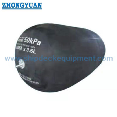
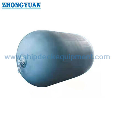
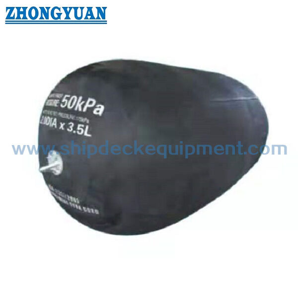
ISO 17357-1 Floating Pneumatic Rubber Fender for Ship-to-Ship and Berthing is a high-pressure floating fender family using compressed air inside a synthetic-tyre-cord-reinforced rubber body to absorb berthing energy. The supplied standard basis covers Type I Net-type, Type I Single and Type II Sling-type configurations with Pneumatic 50 and Pneumatic 80 initial internal pressures.
This page is the technical hub for the high-pressure family. It publishes the ISO 17357-1 performance and pressure requirements, while the separate Type I Net and Type II Sling pages focus on protection-net construction, handling and application differences.
Quick Specifications
- Standard basis: ISO 17357-1:2014 – high-pressure floating pneumatic rubber fenders
- Standard high-pressure types: Type I Net-type | Type I Single | Type II Sling-type
- Initial internal pressure: Pneumatic 50 = 50 kPa | Pneumatic 80 = 80 kPa
- Standard performance point: GEA at 60 ± 5% deflection
- Main performance terms: Guaranteed Energy Absorption (GEA) | Reaction Force | Internal / Hull Pressure
- Standard size table used on this page: 500 × 1000 to 4500 × 12000 mm
- Safety valve: required by ISO 17357-1 for fenders 2500 mm diameter and larger; smaller sizes may use one when specified
Structure & Configuration
Outer rubber | synthetic-tyre-cord reinforcement layers | inner rubber | flange opening and bead-ring / metal end parts | air valve | safety valve where required | Type I protection net or Type II lifting / sling arrangement.
Type I Net-type uses a chain, wire or fibre protection net, normally with tyres / rubber sleeves where applicable. Type I Single has one end without a flange opening or metal parts. Type II Sling-type is designed for use without a protection net.
Main Technical Parameters:
| Pneumatic 50 fender size and performance requirements | ||||
| Nominal size diameter x length mm |
Initial Internal pressure kPa |
Guaranteed energy absorption (GEA) |
Reaction force at GEA deflection (R) |
Hull pressure (Internal pressure) at GEA deflection (P) |
| Minimum value at deflect10n 6 0 土 5 % kj |
Tolerance 土 10 % kN |
Reference value kPa |
||
| 500 X 1 000 | 50 | 6 | 64 | 132 |
| 600 X 1 000 | 50 | 8 | 74 | 126 |
| 700 X 1 500 | 50 | 17 | 137 | 135 |
| 1 000 X 1 500 | 50 | 32 | 182 | 122 |
| 1 000 X 2 000 | 50 | 45 | 257 | 132 |
| 1200 X 2 000 | 50 | 63 | 297 | 126 |
| 1 350 X 2 500 | 50 | 102 | 427 | 130 |
| 1 500 X 3 000 | so | 153 | 579 | 132 |
| 1 700 X 3 000 | 50 | 191 | 639 | 128 |
| 2 000 X 3 500 | 50 | 308 | 875 | 128 |
| 2 500 X 4 000 | 50 | 663 | 1381 | 137 |
| 2 500 X 5 500 | 50 | 943 | 2 019 | 148 |
| 3 300 X 4 500 | 50 | 1175 | 1884 | 130 |
| 3 300 X 6 500 | 50 | 1814 | 3 015 | 146 |
| 3 300 X 10 600 | 50 | 3 067 | 5 257 | 158 |
| 4 500 X 9 000 | 50 | 4 752 | 5 747 | 146 |
| 4 500 X 12 000 | 50 | 6 473 | 7 984 | 154 |
| Pneumatic 50 fender pressure requirements | ||||||
|
Nominal size
|
Internal pressure | Minimum endurable pressure | Safety-valve pressure setting |
Testing pressure at 0% deflect10n |
||
| at 0% deflection kPa |
at 60 % deflection kPa |
at 0% deflection kPa |
at 60 % deflection kPa |
kPa | kPa | |
| 500 X 1 000 | 50 | 132 | 300 | 462 | - | 200 |
| 600 X 1 000 | so | 126 | 300 | 441 | - | 200 |
| 700 X 1 500 | 50 | 135 | 300 | 473 | - | 200 |
| 1 000 X 1 500 | 50 | 122 | 300 | 427 | - | 200 |
| 1 000 X 2 000 | so | 132 | 300 | 462 | - | 200 |
| 1200 X 2 000 | 50 | 126 | 300 | 441 | - | 200 |
| 1 350 X 2 500 | so | 130 | 300 | 455 | - | 200 |
| 1500 X 3 000 | so | 132 | 300 | 462 | - | 200 |
| 1 700 X 3 000 | 50 | 128 | 300 | 448 | - | 200 |
| 2 000 X 3 500 | 50 | 128 | 300 | 448 | - | 200 |
| 2 500 X 4 000 | 50 | 137 | 350 | 480 | 175 | 250 |
| 2 500 X 5 500 | 50 | 148 | 350 | 518 | 175 | 250 |
| 3 300 X 4 500 | 50 | 130 | 350 | 455 | 175 | 250 |
| 3 300 X 6 500 | 50 | 146 | 350 | 511 | 175 | 250 |
| 3 300 X 10 600 | 50 | 158 | 350 | 553 | 175 | 250 |
| 4 500 X 9 000 | 50 | 146 | 350 | 511 | 175 | 250 |
| 4 500 X 12 000 | so | 154 | 350 | 539 | 175 | 250 |
Selection & Inquiry Guide
Step 1 – Confirm service: ship-to-ship transfer, vessel-to-berth, temporary berthing or permanent / semi-permanent installation.
Step 2 – Determine the required GEA from the berthing analysis, then select nominal size and 50 / 80 kPa pressure grade while checking allowable reaction and hull pressure.
Step 3 – Select Type I Net, Type I Single or Type II Sling according to body-protection, handling and mooring requirements.
Step 4 – Confirm safety valve requirement, mooring / guy-chain arrangement, storage / shipping condition and installation accessories.
Step 5 – Define prototype / commercial test certificate, independent inspection and documentation scope before quotation.
Key Engineering Advantages
- Floating installation allows the fender to follow water level and vessel vertical movement over a wide tidal range.
- Compressed-air energy absorption provides a progressive reaction characteristic and distributes contact load over a relatively large hull area.
- 50 and 80 kPa standard pressure grades allow energy/reaction selection within the same nominal size family.
- Type I and Type II configurations allow the same ISO performance framework to be matched to different protection and handling requirements.
Installation / Handling & Maintenance
Pneumatic fenders are normally moored with guy chains or ropes so the body can float and move with the water level. The mooring arrangement should prevent contact with sharp projections and avoid excessive chain / wire abrasion on the rubber body.
Air pressure should be checked at defined maintenance intervals and restored to the specified initial pressure when required. Net condition, lifting eyes, valves, shackles and mooring accessories should be inspected for wear, corrosion or damage. Storage should avoid heat, oil, grease, acids, alkalis and sharp objects.
Inspection & Documentation
|
Inspection Level |
Main Items |
|---|---|
| Prototype performance confirmation | Parallel compression test; angular compression test; durability test; compression-recovery test; puncture-resistance test |
| Commercial fender inspection | Rubber material test; dimensional inspection; air-leakage test; hydrostatic-pressure test |
| Marking / documentation | Standard designation, nominal size, initial pressure, manufacturer identification / serial information and required documentation |
| Independent inspection | Can be specified when required by purchaser / project; scope to be agreed before order |
A user-supplied historical third-party witnessed test report for a 3300 × 6500 mm Pneumatic 50 fender records a 250 kPa hydrostatic pressure test, 482.8 kPa actual endurable / burst result and 174 kPa safety-valve opening pressure. This is retained as supporting test evidence for the supply chain and is not presented as a blanket certificate for every product or order.
Applications
Ship-to-ship transfer | oil & gas terminals | tankers | LNG / LPG operations | ports and jetties | temporary berthing | emergency fendering | offshore transfer
Drawing & Photos

FAQ
Q1: What is the difference between Pneumatic 50 and Pneumatic 80? — The initial internal pressure is 50 or 80 kPa. For the same nominal size, Pneumatic 80 normally provides higher GEA and reaction force.
Q2: Are Net and Sling types different in ISO performance values? — They share the ISO 17357-1 high-pressure performance framework; the main difference is the external protection / handling configuration.
Q3: Is low-pressure 7 kPa included on this page? — No. Low-pressure floating pneumatic fenders belong to ISO 17357-2 and are treated as a separate product family.