


|
Deck-Mounted Ship Towing Bracket with Sliding Pin | JIS F 2029 Emergency Towing Fitting
Product Details:
| Place of Origin: | China |
| Brand Name: | Zhongyuan Marine Equipmen |
| Certification: | CCS, NK, BV, ABS, DNV, LR, KR, IRS, RS, RINA, CRS, Makers Test Certificate |
| Model Number: | Standard or Customized |
Payment & Shipping Terms:
| Minimum Order Quantity: | 1 Unit |
|---|---|
| Price: | Based on quotation |
| Packaging Details: | Export standard pallet or customized packing |
| Delivery Time: | Based on project requirements |
| Payment Terms: | T/T, L/C |
| Supply Ability: | Customized production based on project requirements |
|
Detail Information |
|||
| Standard: | JIS F 2029-1997 | Nominal No.: | 52-132 |
|---|---|---|---|
| Nominal Diameter Of Applicable Anchor Chain: | 50-132mm | Materials: | C-Mn Steel, Mild Steel |
| Weight: | 55 To 723kg | Surface Treatment: | Sandblasting To S2.5 + 3 Layers Of Epoxy Paint, Galvanized |
| Classification Certificates: | CCS, NK, BV, ABS, DNV, LR, KR, RINA, IRS, RS, Etc | ||
| Highlight: | Towing JIS F 2029-1997 mooring bracket,JIS F 2029-1997 mooring bracket,JIS F 2029 Ship Towing Equipment |
||
Product Description
Deck-Mounted Ship Towing Bracket with Sliding Pin | JIS F 2029 Emergency Towing Fitting
Product Overview
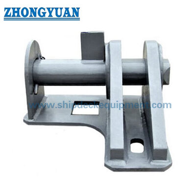
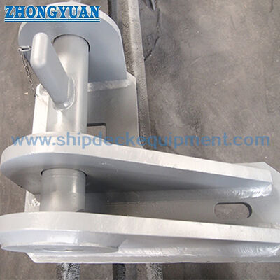
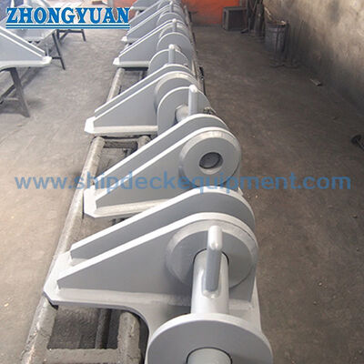
The JIS F 2029 deck-mounted ship towing bracket is a welded connection fitting used to secure the end link of a chafing chain in an emergency towing arrangement. Its main structure consists of two parallel vertical eye plates on a base plate, a transverse sliding pin passing through the chain end link, a pin support plate, and a stopper pin for retention.
The supplied JIS F 2029-1997 range covers nominal numbers 52 to 132 for applicable anchor-chain diameters from 50 to 132 mm. The bracket is normally arranged on the forecastle deck or another approved towing strong-point location according to the vessel design. It is not a general mooring bollard or rope-guiding chock. Final selection must consider chain grade and end-link geometry, approved towing load, line of pull, pin and plate materials, deck reinforcement, welding details, access for pin handling, and classification requirements.
Quick Specifications
- Product type: Deck-mounted ship towing bracket → secures the chafing-chain end link within an approved emergency towing arrangement.
- Structure: Parallel eye plates + transverse sliding pin + pin support plate + stopper pin → provides a positive chain-end connection with a removable main pin.
- Standard reference: JIS F 2029-1997 → project-adopted edition and official standard status should be confirmed before final datasheet release.
- Nominal range: No. 52 to No. 132 → corresponds to applicable anchor-chain diameters from 50–52 mm up to 124–132 mm.
- Calculated mass: 55 to 723 kg → supports handling, transport, installation planning, and preliminary freight estimation.
- Installation: Welded base plate on reinforced deck structure → bracket load path, weld details, and local deck reinforcement require vessel-design approval.
- Material options: C-Mn steel or mild steel as supplied information → exact plate, pin, support-plate, and stopper-pin grades must be confirmed separately.
- Load basis: No SWL or towing design load is provided in the supplied table → chain diameter is a dimensional selection reference, not a substitute for approved towing-load verification.
Main Technical Parameters
| Nominal No |
Nominal dia. of applicable anchor chain |
Base plate |
Pin | Weld Leg Length |
|||||||||||||||
| L1 | L2 | L4 | B | B1 | B2 | t3 | D | L | l | l1 | l2 | l3 | t4 | h | d1 | f | f1 | ||
| 52 | 50 to 52 | 425 | 470 | 95 | 70 | 165 | 230 | 12 | 65 | 430 | 80 | 175 | 175 | 135 | 32 | 100 | 13 | 10 | 7 |
| 56 | 54 to 56 | 450 | 500 | 100 | 75 | 180 | 250 | 14 | 70 | 455 | 80 | 190 | 185 | 145 | 32 | 110 | 13 | 11 | 7 |
| 60 | 58 to 60 | 475 | 540 | 115 | 80 | 195 | 260 | 16 | 75 | 475 | 80 | 200 | 195 | 155 | 32 | 120 | 13 | 12 | 8 |
| 64 | 62 to 64 | 500 | 580 | 120 | 85 | 205 | 270 | 16 | 80 | 505 | 80 | 215 | 210 | 170 | 32 | 130 | 13 | 12 | 8 |
| 68 | 66 to 68 | 530 | 610 | 125 | 90 | 220 | 300 | 19 | 85 | 525 | 80 | 225 | 220 | 175 | 32 | 140 | 16 | 13 | 9 |
| 73 | 70 to 73 | 560 | 660 | 130 | 100 | 235 | 310 | 19 | 90 | 560 | 80 | 245 | 230 | 190 | 32 | 150 | 16 | 14 | 9 |
| 78 | 76 to 78 | 600 | 700 | 140 | 105 | 260 | 340 | 22 | 95 | 590 | 80 | 260 | 250 | 200 | 32 | 160 | 16 | 15 | 10 |
| 84 | 81 to 84 | 620 | 760 | 150 | 110 | 270 | 360 | 22 | 100 | 615 | 80 | 275 | 260 | 210 | 32 | 170 | 16 | 16 | 10 |
| 90 | 87 to 90 | 695 | 810 | 160 | 120 | 295 | 390 | 25 | 110 | 685 | 100 | 300 | 285 | 235 | 40 | 180 | 16 | 17 | 10 |
| 95 | 92 to 95 | 725 | 860 | 170 | 130 | 305 | 410 | 25 | 120 | 720 | 100 | 320 | 300 | 245 | 40 | 190 | 19 | 18 | 11 |
| 102 | 97 to 102 | 765 | 920 | 185 | 135 | 330 | 440 | 28 | 130 | 745 | 100 | 330 | 315 | 260 | 40 | 205 | 19 | 19 | 11 |
| 111 | 105 to 111 | 805 | 1000 | 200 | 145 | 350 | 470 | 28 | 140 | 790 | 100 | 355 | 335 | 280 | 40 | 220 | 19 | 20 | 11 |
| 120 | 114 to 120 | 850 | 1080 | 220 | 160 | 370 | 510 | 28 | 150 | 845 | 100 | 385 | 360 | 305 | 40 | 240 | 19 | 21 | 11 |
| 132 | 124 to 132 | 910 | 1200 | 240 | 175 | 395 | 560 | 30 | 160 | 905 | 100 | 415 | 385 | 330 | 40 | 260 | 19 | 22 | 11 |
| Nominal No |
Nominal dia. of applicable anchor chain |
Eye plate |
Pin support plate |
Stopper Pin |
Calculated Mass |
||||||||
| L3 | H | D1 | D3 | R | t | t1 | D2 | S | e | l4 | |||
| 52 | 50 to 52 | 415 | 130 | 70 | 160 | 95 | 22 | 14 | 72 | 245 | 15 | 115 | 55 |
| 56 | 54 to 56 | 450 | 140 | 75 | 170 | 100 | 25 | 14 | 77 | 255 | 15 | 120 | 70 |
| 60 | 58 to 60 | 480 | 150 | 80 | 180 | 105 | 25 | 16 | 82 | 265 | 15 | 130 | 83 |
| 64 | 62 to 64 | 510 | 160 | 85 | 190 | 110 | 28 | 16 | 87 | 280 | 15 | 135 | 99 |
| 68 | 66 to 68 | 545 | 170 | 90 | 200 | 120 | 28 | 19 | 92 | 290 | 18 | 145 | 121 |
| 73 | 70 to 73 | 585 | 180 | 95 | 220 | 130 | 30 | 19 | 97 | 305 | 18 | 150 | 144 |
| 78 | 76 to 78 | 625 | 195 | 100 | 230 | 135 | 32 | 22 | 102 | 320 | 18 | 160 | 180 |
| 84 | 81 to 84 | 670 | 210 | 105 | 250 | 145 | 35 | 22 | 107 | 330 | 18 | 165 | 219 |
| 90 | 87 to 90 | 720 | 225 | 115 | 270 | 160 | 38 | 25 | 117 | 375 | 18 | 180 | 280 |
| 95 | 92 to 95 | 760 | 235 | 120 | 280 | 170 | 38 | 28 | 127 | 390 | 21 | 190 | 321 |
| 102 | 97 to 102 | 815 | 255 | 135 | 300 | 180 | 40 | 28 | 137 | 405 | 21 | 205 | 386 |
| 111 | 105 to 111 | 890 | 275 | 145 | 330 | 190 | 45 | 28 | 147 | 425 | 21 | 215 | 465 |
| 120 | 114 to 120 | 960 | 300 | 155 | 350 | 205 | 50 | 30 | 157 | 450 | 21 | 230 | 586 |
| 132 | 124 to 132 | 1050 | 330 | 165 | 390 | 225 | 50 | 35 | 167 | 480 | 21 | 245 | 723 |
Selection & Inquiry Guide
Step 1: Confirm JIS F 2029, nominal number 52–132, applicable chain diameter, chain grade, and the actual end-link dimensions.
Step 2: Confirm the bracket function within the vessel emergency towing arrangement, installation position, towing direction, line-of-pull angle, and available working access.
Step 3: Provide the approved towing design load, chain MBL or project load basis, required safety factors, and any test-load requirement; do not derive SWL from nominal number alone.
Step 4: Confirm base-plate, eye-plate, pin, support-plate, and stopper-pin materials, including low-temperature or special-service requirements where applicable.
Step 5: Confirm deck reinforcement, foundation drawing, weld preparation, weld-leg dimensions f / f1, WPS requirement, inspection scope, and access for sliding-pin removal and retention.
Step 6: Confirm surface treatment, final vessel coating system, corrosion protection around the removable pin, material traceability, class society, and certificate scope.
Step 7: Provide quantity, official standard drawing or GA drawing, installation photos if available, delivery destination, required delivery time, and packing or transport limitations.
Structure
Welded base plate | Two parallel vertical eye plates | Transverse sliding main pin | Pin support plate | Stopper pin | Chain end-link engagement space | Deck welding interface | Specified corrosion-protection system
Towing Connection, Welding & Engineering Advantages
- The transverse sliding pin forms a direct mechanical connection through the chafing-chain end link, avoiding the incorrect use of a rope-guiding fitting as the towing connection point.
- Parallel eye plates support the pin on both sides of the chain link; plate spacing, hole alignment, and pin fit should be controlled to prevent installation interference and uneven local bearing.
- The pin support plate and stopper pin provide handling and retention functions, but the final retention arrangement and removal direction must remain accessible in the installed deck layout.
- The welded base plate transfers towing reactions into the vessel structure. Deck plating, under-deck stiffening, brackets, weld length, and load direction must be verified by the ship designer or classification society.
- The standard size range provides dimensional compatibility for several anchor-chain diameters, while final suitability still depends on chain grade, end-link form, project towing load, and approved emergency towing arrangement.
- Pin surface condition, edge radii, hole finish, and corrosion protection should be controlled so that the chain link can be connected and disconnected without damage or avoidable seizure.
- Material traceability, dimensional inspection, welding control, and project-specific examination can be arranged according to the agreed inspection and certification scope.
Custom Attributes
- Standard: JIS F 2029-1997 → use when the vessel or shipyard specification adopts the JIS towing-bracket dimensional series.
- Nominal Number: 52 / 56 / 60 / 64 / 68 / 73 / 78 / 84 / 90 / 95 / 102 / 111 / 120 / 132 → select initially by the applicable chain-diameter range.
- Applicable Chain Diameter: 50–132 mm overall range → actual chain grade and end-link geometry must also be confirmed.
- Connection Method: Sliding transverse pin through the chain end link → pin diameter and fit follow the selected nominal number and approved drawing.
- Installation: Deck welded → local deck reinforcement, weld details, and towing-load direction require project approval.
- Material: C-Mn steel / mild steel as supplied information → individual component grades and pin properties are to be confirmed.
- Surface Treatment: Sa 2.5 blasting + epoxy shop primer as reference → final coating follows the vessel painting specification.
- Certificate Requirement: Available according to project scope → material certificates, maker documentation, class inspection, and test witnessing must be confirmed before quotation.
How It Works
Chafing-chain end link is positioned between the parallel eye plates → Sliding pin passes through the eye plates and chain link → Stopper pin retains the main pin → Towing force transfers from the chain through the pin and eye plates → Welded base and reinforced deck structure carry the reaction into the vessel
Applications
Emergency towing arrangements | Forecastle deck towing stations | Tankers and cargo vessels where the approved arrangement specifies this bracket | Newbuilding projects | Replacement and retrofit projects subject to drawing confirmation
Certifications & Advantages
Certificates and inspection documentation can be arranged according to project requirement, material traceability, approved drawing, inspection scope, and classification-society procedure. Class approval and witness testing are not included by default unless stated in the order.
Certification: CCS, NK, BV, ABS, DNV, LR, KR, IRS, RS, RINA, CRS, Makers Test Certificate.
Drawing & Photos

FAQ
Q1: Is the JIS F 2029 bracket a mooring bollard or rope guide?
A1: No. It is a towing connection fitting for securing the end link of a chafing chain with a transverse pin. It should not be described as a bollard, chock, fairlead, or general rope-guiding component.
Q2: Can the bracket be selected only by anchor-chain diameter?
A2: Chain diameter is the initial dimensional reference. Final selection must also confirm chain grade, end-link dimensions, towing design load, line of pull, pin and plate materials, deck reinforcement, weld details, and class approval requirements.
Q3: What information is required before quotation?
A3: Confirm JIS F 2029 nominal number, chain specification and end-link drawing, towing load basis, installation position, load direction, material grades, deck foundation, welding and inspection requirements, coating system, certificate scope, quantity, destination, and delivery schedule.